Astro
PROJECT ROLE: PRINCIPAL MECHANICAL ENGINEER
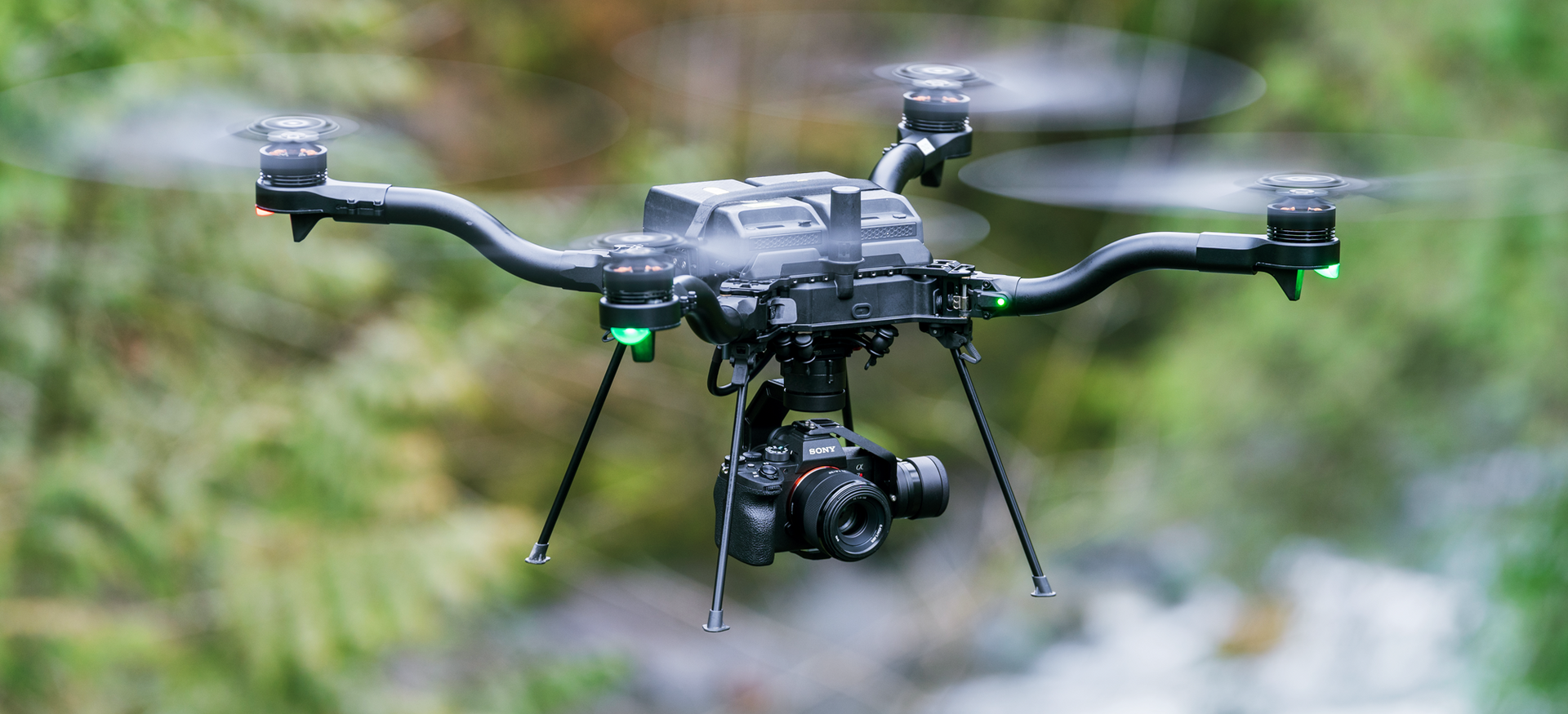
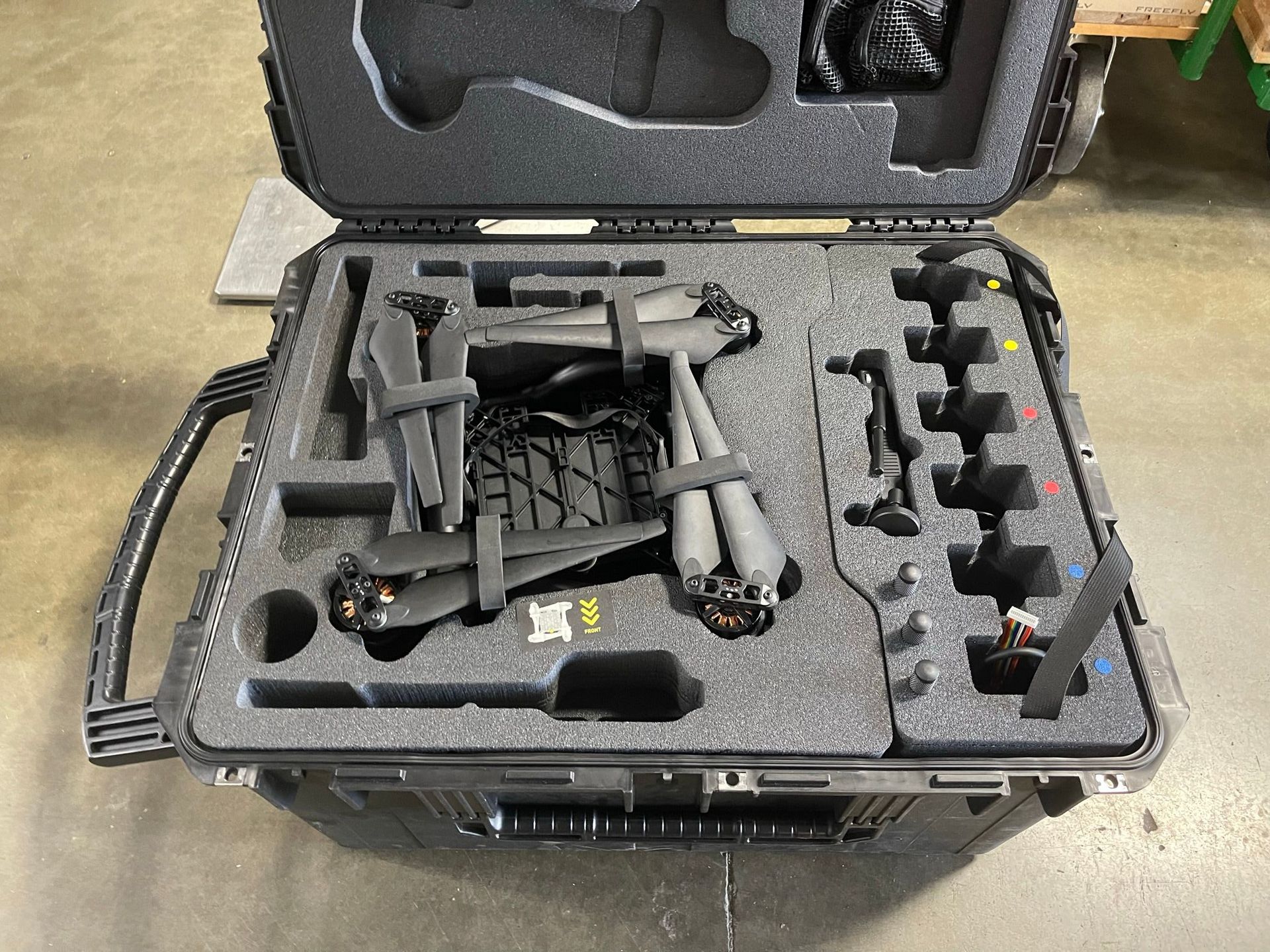
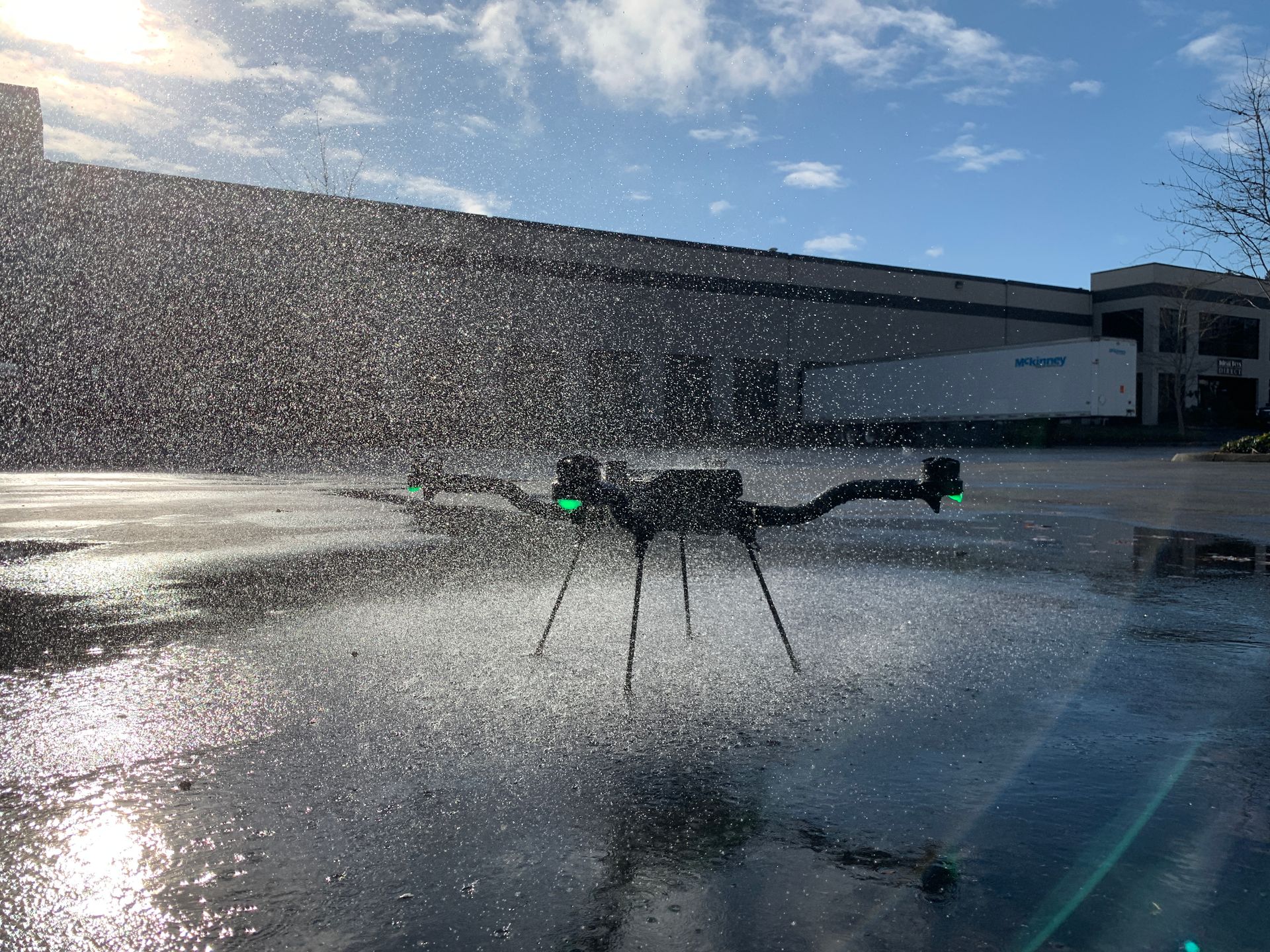
After a long and successful history creating UAS that were mainly designed for the Hollywood film industry, the Astro became the first Freefly Systems UAS that catered directly to an industrial user. This change in user base came with an exciting new set of design problems which I took on as Astro's Principal Mechanical Engineer.
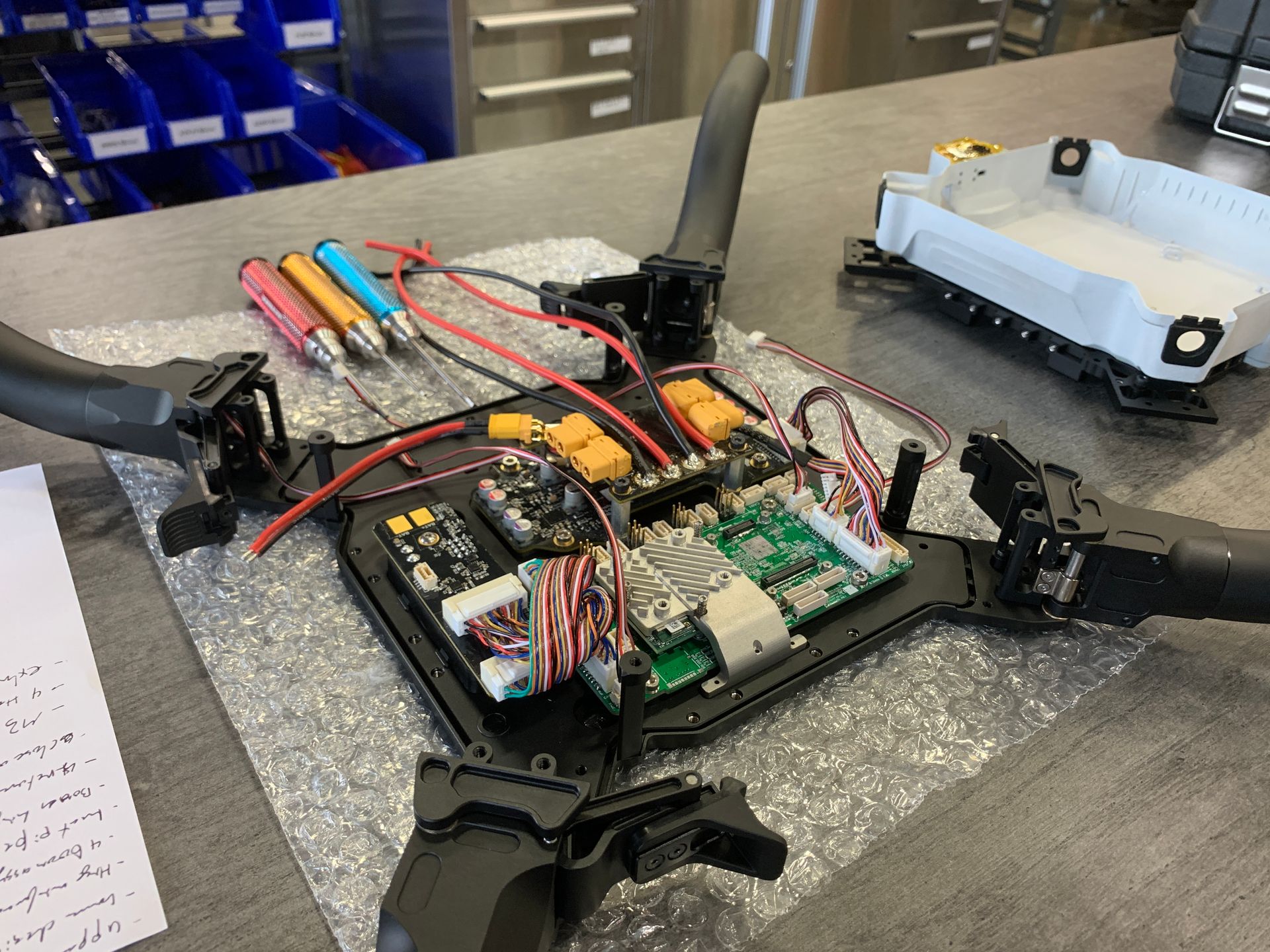
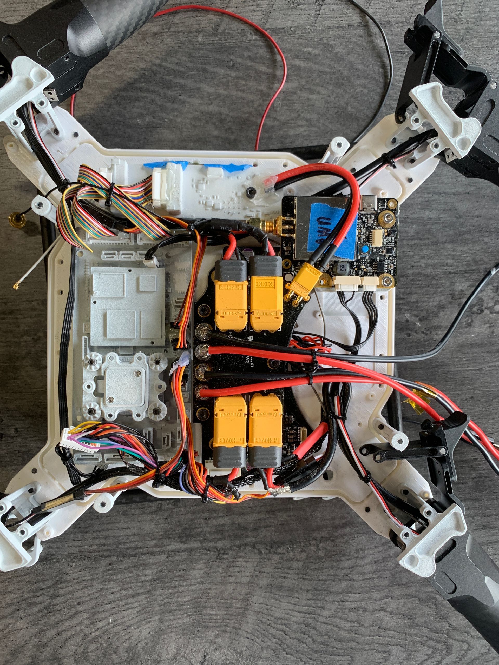
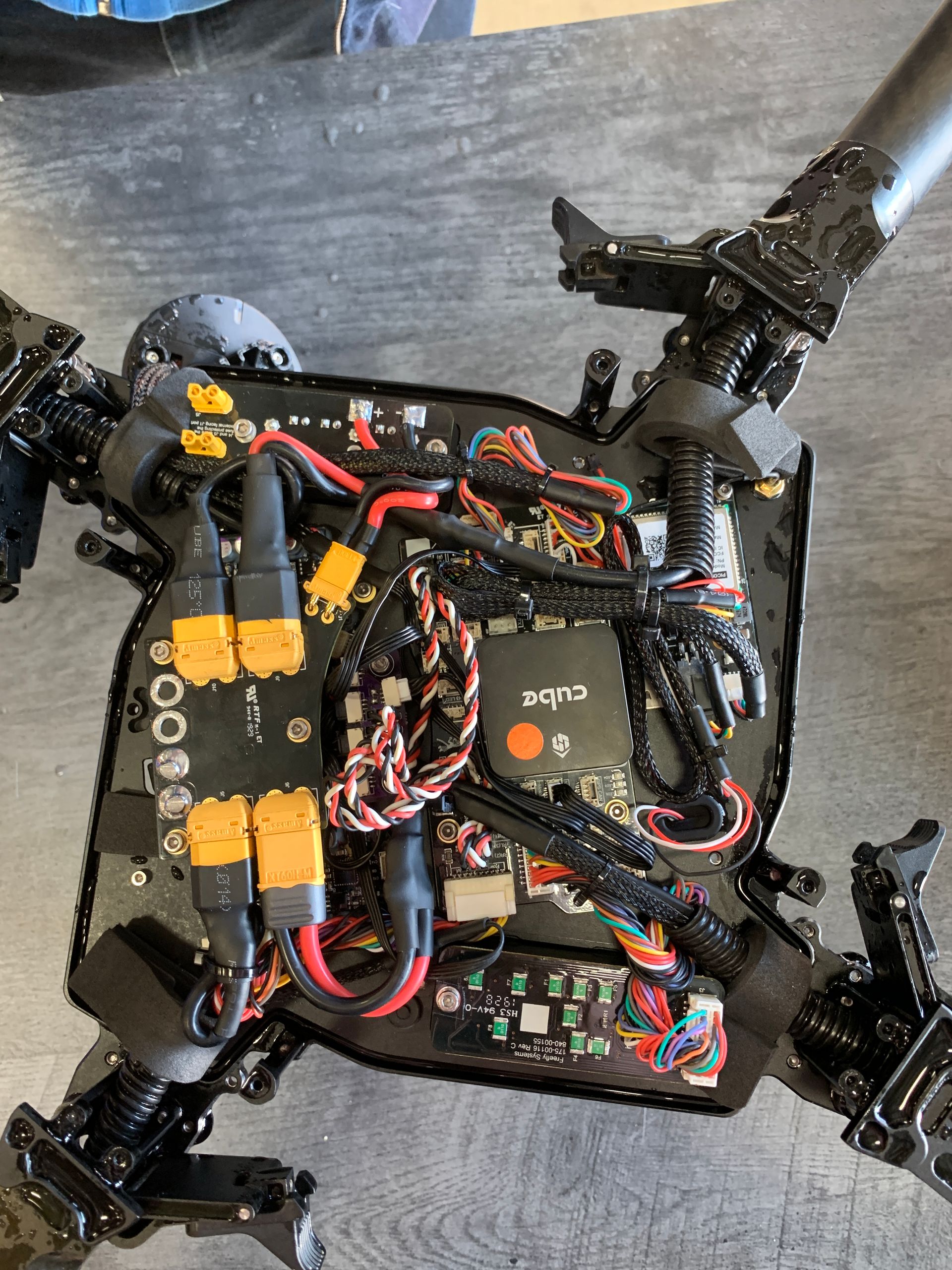
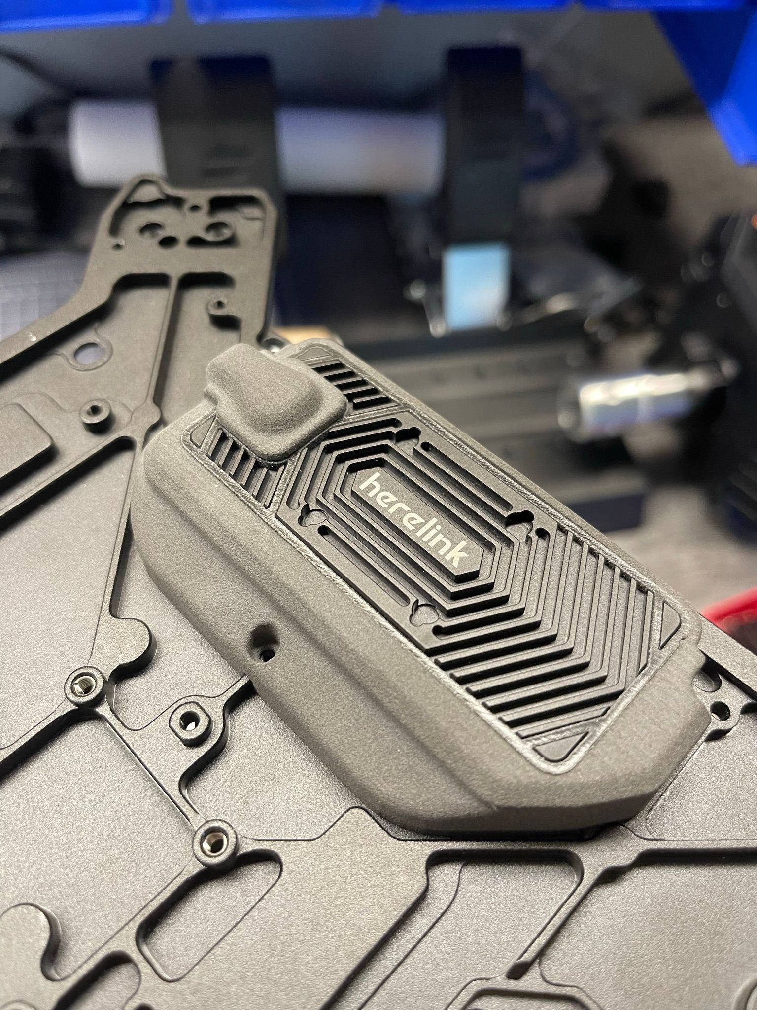
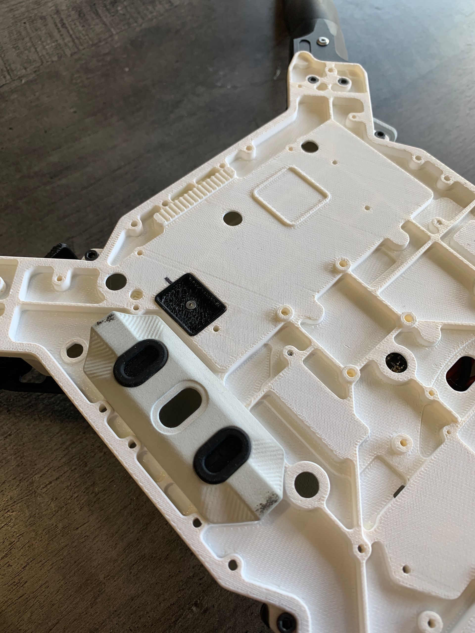
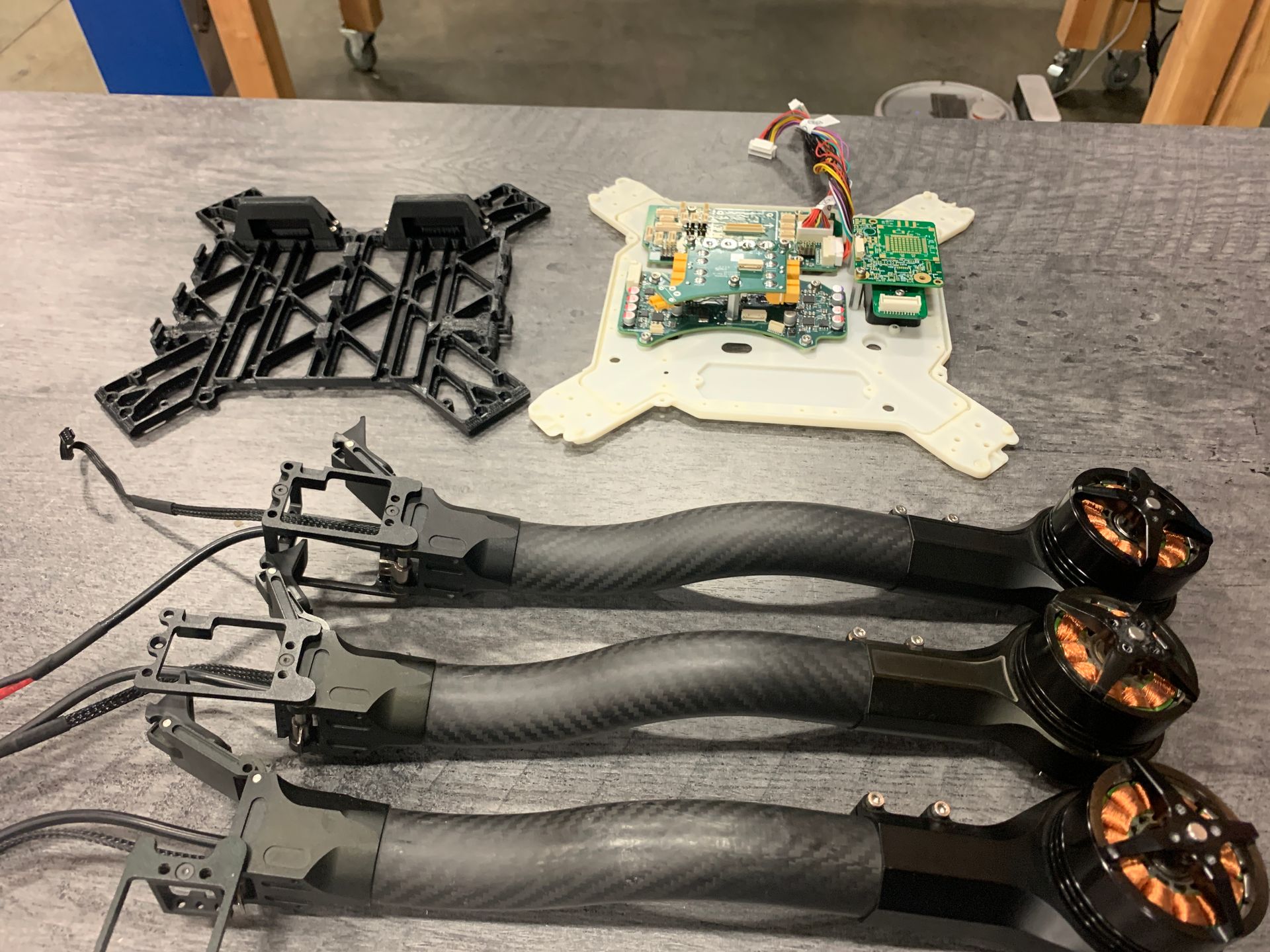
As the Principal Mechanical Engineer, I owned Astro's design while leading a team of four mechanical engineers. I simultaneously developed the detailed design work for critical elements such as the lower chassis, payload interface, boom hinge, and electronics packaging, engineering each component to meet the stringent demands of industrial clients. Once the design work concluded I led two rigorous testing phases, coordinating with the entire cross-functional team of thirteen to complete more than 200 tests to validate the UAS's reliability and ensure that it met our high bar for performance and reliability. On the production front, I designed and optimized the entire manufacturing flow, created work instructions, and implemented quality control measures. This work ultimately culminated in the meticulous final inspection of the first 100 units to each customer's success. As a key part of the project management team, I led the effort of four other mechanical engineers, coordinated timelines with other cross-functional leads, managed the engineering bill of material and supply chain during the active design phases of the project, and took ownership of the Astro Design Review meetings ensuring they were impactful and led to continued refinement of Astro.
It has been incredible to see the different ways the Astro platform has successfully integrated in different industries: tracking endangered wildlife such as whales and koalas, providing aerial support to firefighters battling remote wildfires, and providing a means to safely inspect or map infrastructure all over the world. I am proud each time I see a new integration since it means that the decisions I made as Astro's Principal Mechanical Engineer helped someone say 'Yes' to solving a problem.
Team Size
11
Budget
$950k
Part Count
1050
Total Flights
+100,000
Key Challenges
Taking Charge
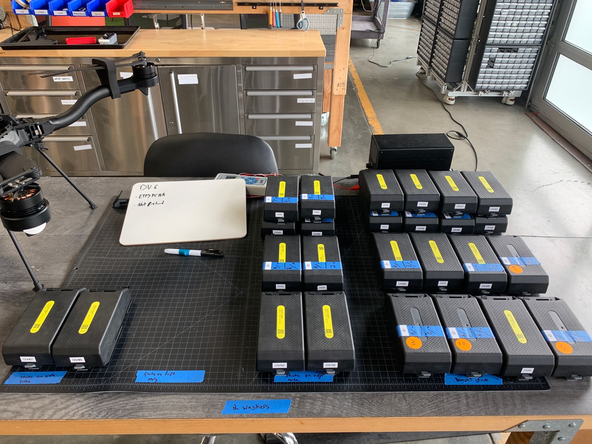
Our first iteration of Astro was designed to use an off-the-shelf battery. However we quickly identified that we could not rely on another party to design one of the most critical aspects of Astro. This expanded Astro's design scope to include a clean sheet design smart battery. The battery would need to function day in, day out, in some of the roughest environmental conditions while still being light, easy to use, and powerful enough to last on a single battery.
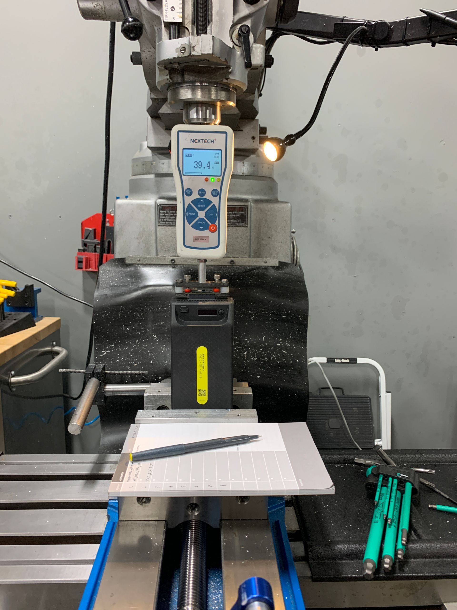
During our validation phase of our new smart battery we discovered that due to the amount of friction the connector had on insertion, a user could partially install the battery without being fully latched, risking battery ejection due to vibrations encountered during flight. The connector force would also increase over time due to wear and environmental contaminants, causing battery ejection to fail when unlatched. Additionally we found a consequential number of batteries with connectors that were chipped and damaged after being used with aircraft.
Once a change in connector was ruled out and the project timeline began to slip, I took the lead on finding a solution to these problems. After analyzing the problem, I completed some initial testing on current per connector contact and performed a tolerance stackup analysis. Based on these findings, I recommended that we remove a set of battery contacts to reduce the amount of connector force, add a shim to raise the aircraft side connector as it had been designed with a one-sided tolerance, and change the latching profile on the top chassis plate to prevent the split line on the molded latching part from finding enough purchase to get stuck. With the implementation of these changes, we were able to pass both the installation and ejection criteria for a battery's entire 500 cycle life.
One Interface to Rule Them All
A new payload interface design was required to make use of Astro's powerful flight controller and internal Linux computer. To make the most of this brand new interface, an ambitious set of requirements was developed from the project onset:
- 40 electrical signals needed to run through the connector and the interface has a lifecycle over 2500 connections.
- It required a safety that would automatically engage when the payload was inserted in addition to a second action that would fully secure the interface.
- The entire design needed to be simple enough to be made into a standard that 3rd party drone or payload manufacturers could successfully interface with or fully recreate.
- The user needed to be able to operate the interface with a single gloved hand.
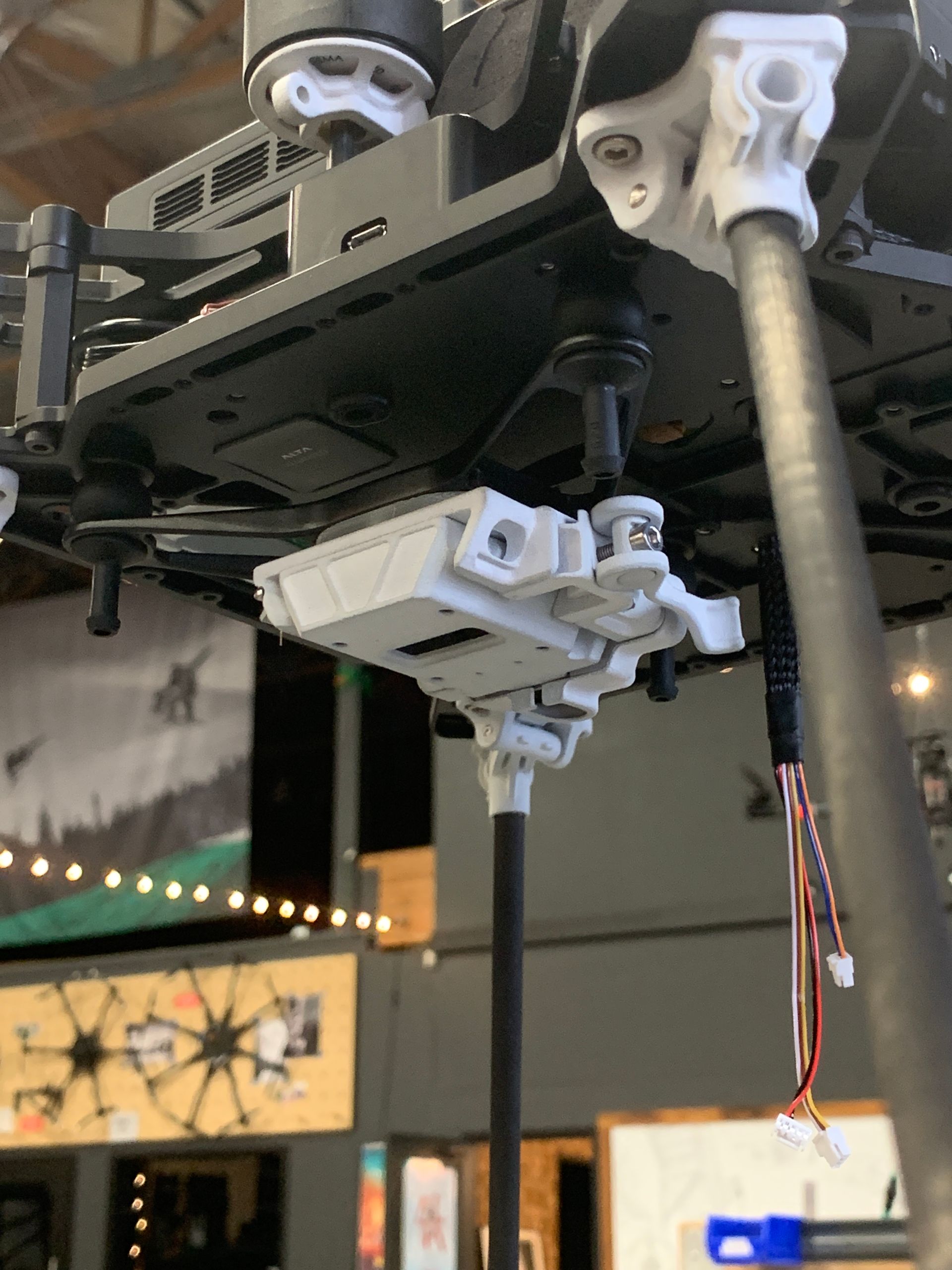
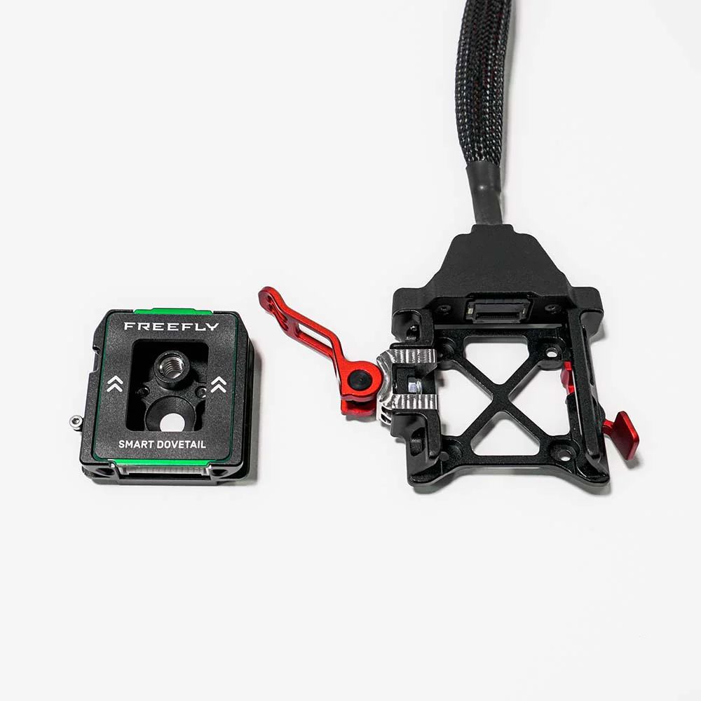
To make sure that the payload interface could accomplish all of these requirements I designed a sliding dovetail quick release with a spring loaded safety that would engage at the point where two halves of the connector made full electrical contact. The whole interface would be secured using an over-center clamp. Due to the nature of such an interface, it needed to account for a large tolerance stackup to ensure the connector did not bind or damage itself during installation or when the overcenter clamp was engaged. To account for this stackup, I chose a connector that had 0.5mm of float in the X and Y axes and added a molded part to the system to increase the compliance by 0.5mm in the X, Y, and Z axes. The molded part was designed to deflect first and then minimize the forces applied to the connector itself, thus increasing its lifetime.
Once the interface was designed and tested it was added to the Pixhawk Payload Bus Standard as its official mechanical interface standard. As of the start of 2024 this interface is being used by four other payload manufacturers to mount and control lidar, SLAM payloads, and a variety of gimbals as well as another drone manufacturer for its payload interface.
When Design get Stressful
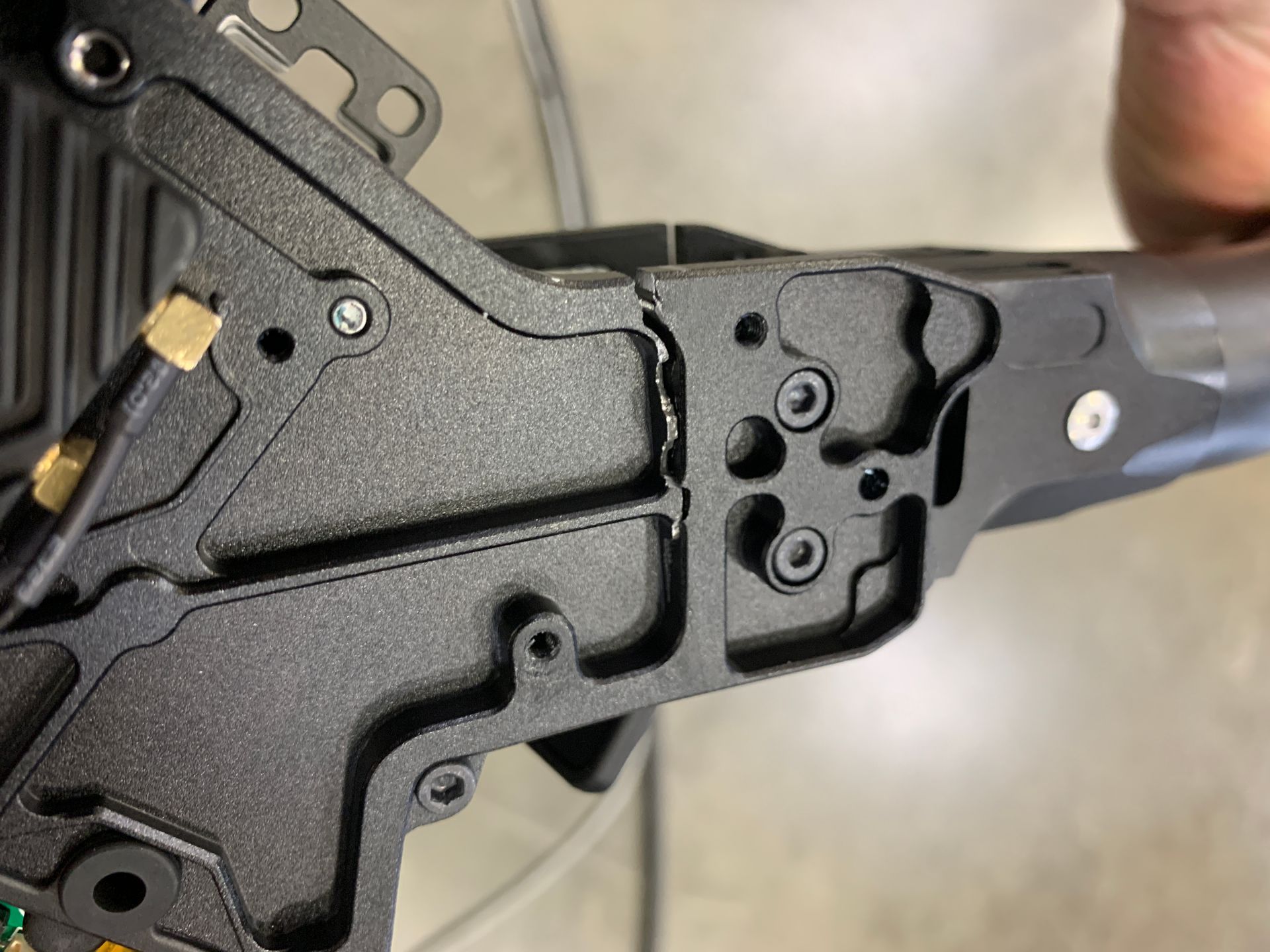
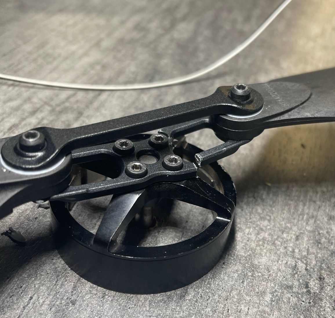
Much of Astro is made from 6061 aluminum as it is easy to machine, lightweight, and relatively inexpensive. However this choice of material came with a drawback: that part fatigue is not a question of ‘if’ but rather 'when' . To ensure Astro would not have any part fatigue during its lifetime, I identified the parts and assemblies that would require detailed analysis and tests; these included the upper/lower chassis plates, prop adapters, and boom hinges.
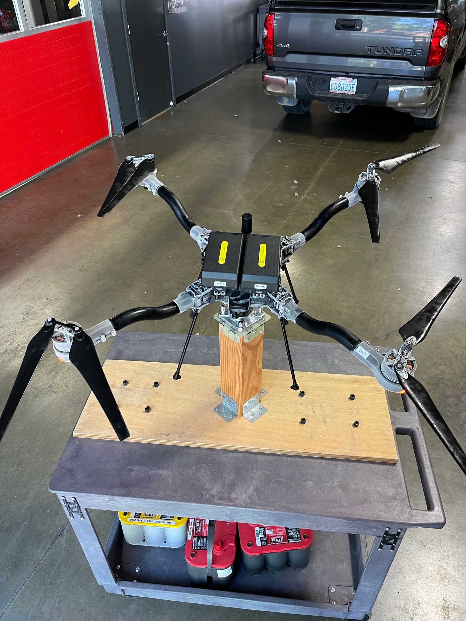
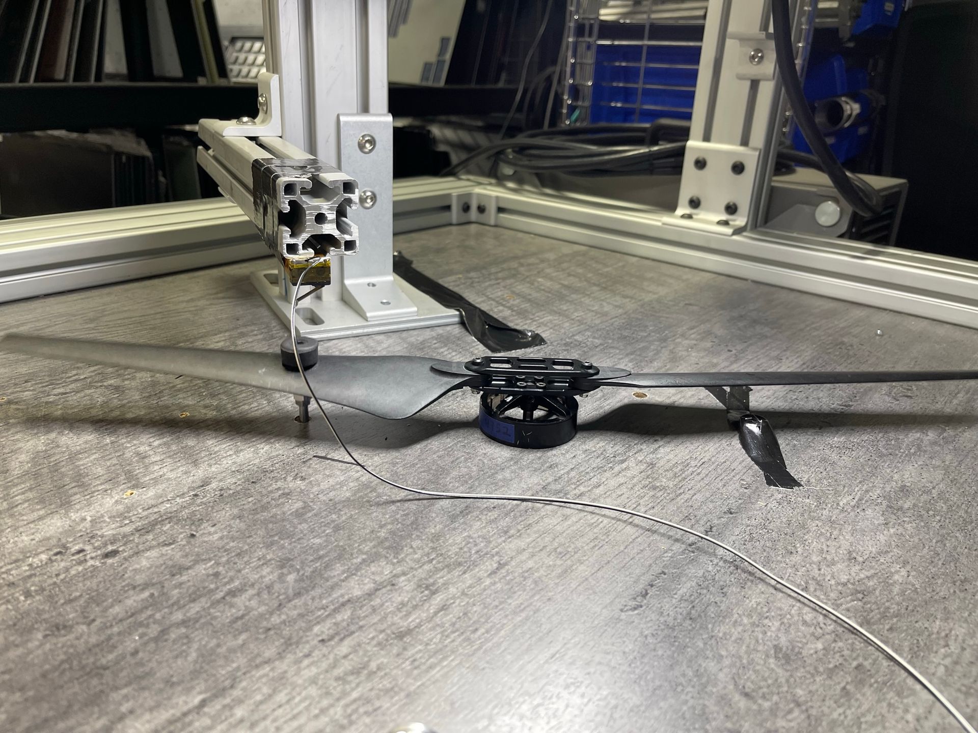
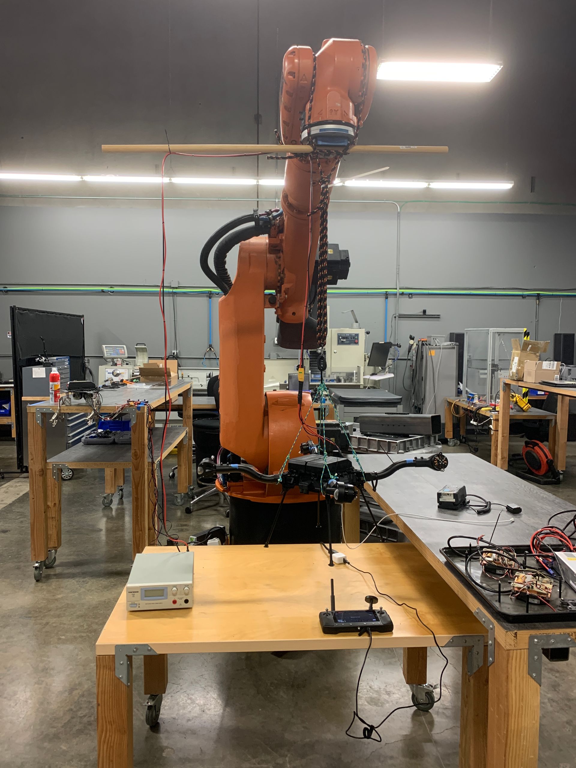
I used various methods to ensure that my parts would meet Astro's 5 year lifetime warranty with an additional safety factor of 1.5 to avoid failure events for our users. The most efficient check performed was a static load calculation for the prop adapters and the boom hinge assemblies; this would highlight any obvious issues with the design and give us an indication the parts would stand up to continuous flight loading. Once acceptable static load stress was reached, I captured the vibration data from an out of balance propeller during an aggressive flight and set up a test where I used offset weights and motor clocking to recreate the worst case instances captured during the data logging flight. This test was run for over 100hrs until the number of cycles in this worst case state met our estimated cycle count from an aircraft that was being flown in an extreme manner for 7.5yrs of flights.
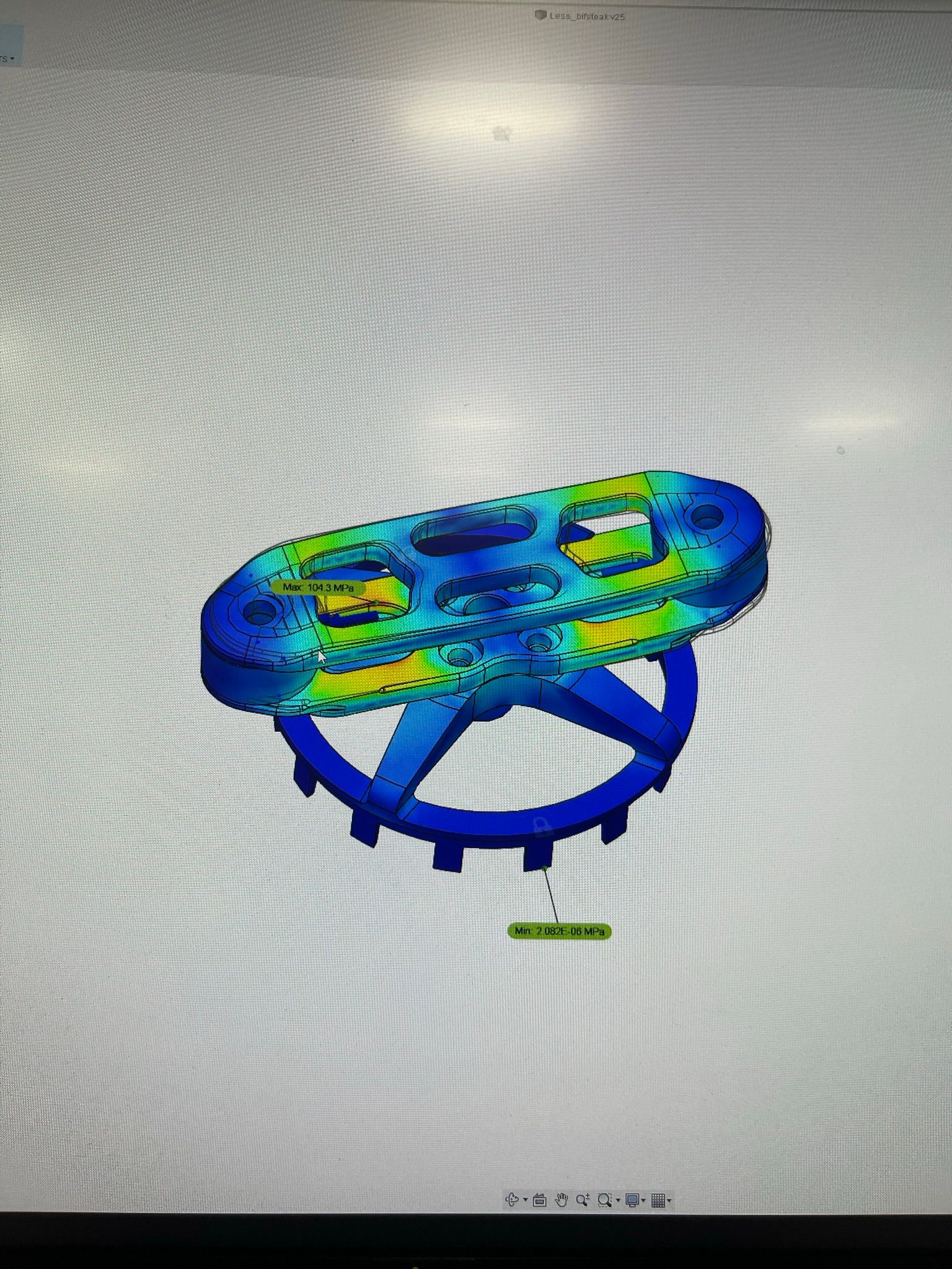
Before starting to empirically test the prop adapters, I ran an additional set of calculations to determine the dissymmetry of lift, which is an important part of the the forces that act on the prop adapter. This dissymmetry is a result of the difference in relative airspeed that the advancing and retreating prop blades experience, and ends up imparting a high count cyclical load to the prop adapter. Once I calculated these forces for Astro's top speed, I was able to run Finite Element Analysis (FEA) to ensure that the prop adapter design would stand up to the empirical validation test and flight hours we would subject it to.
