MINI GIMBAL
PROJECT ROLE: MECHANICAL ENGINEER then PRINCIPAL ENGINEER
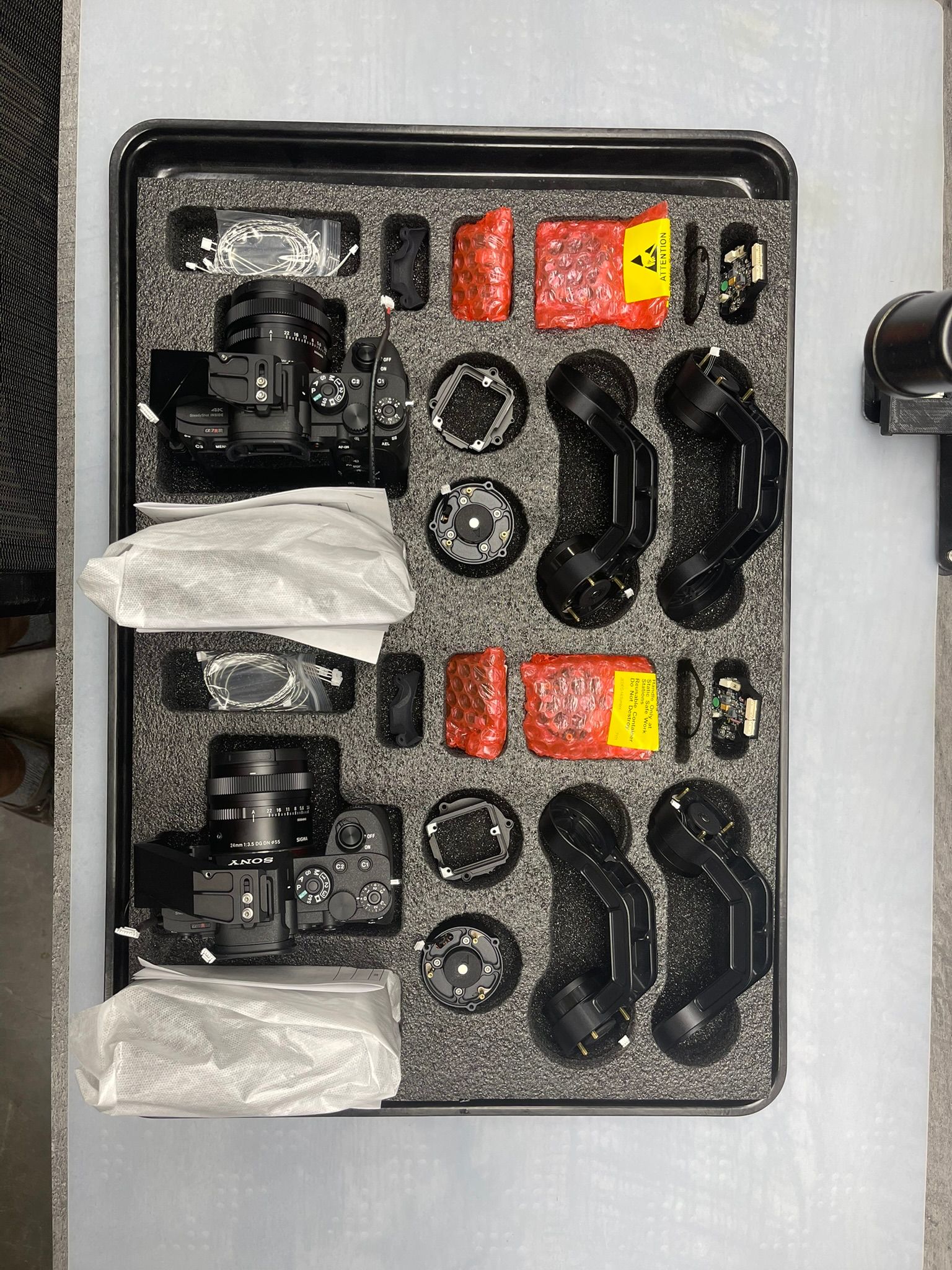
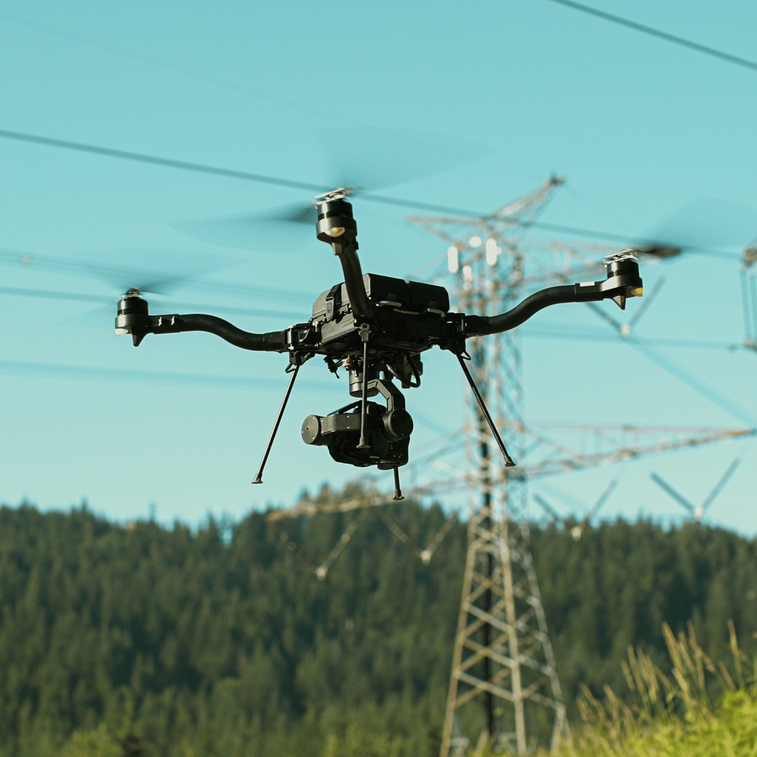
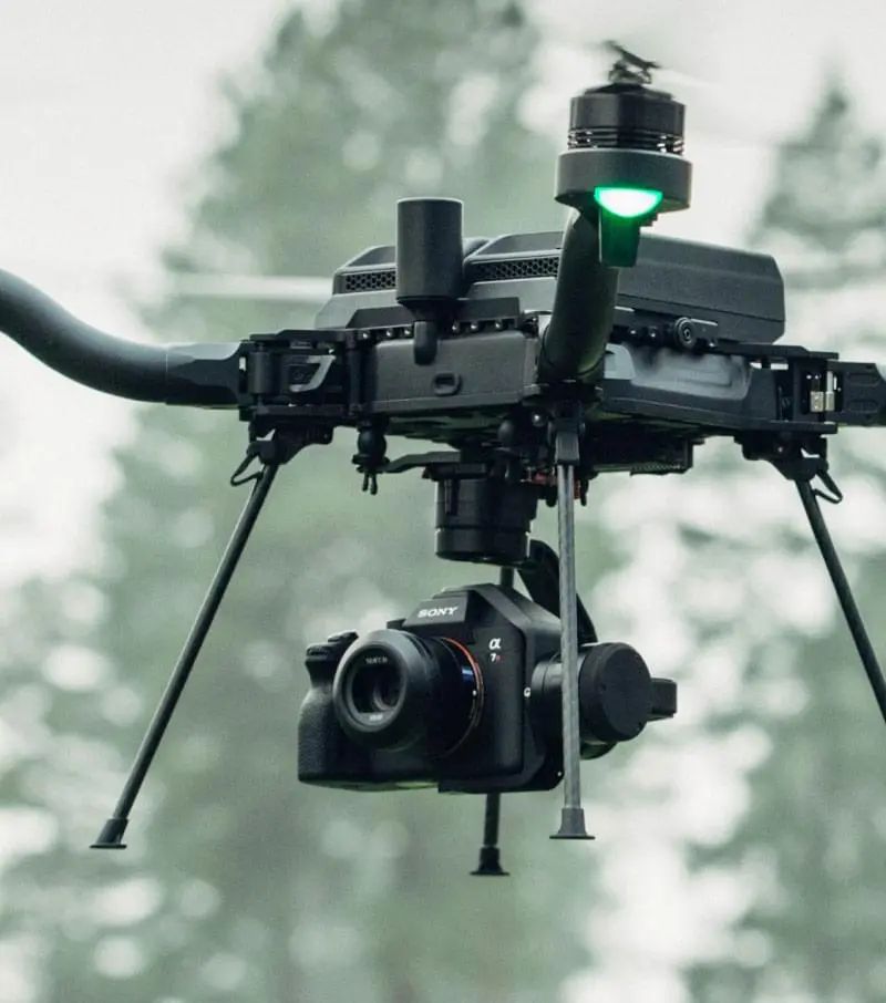
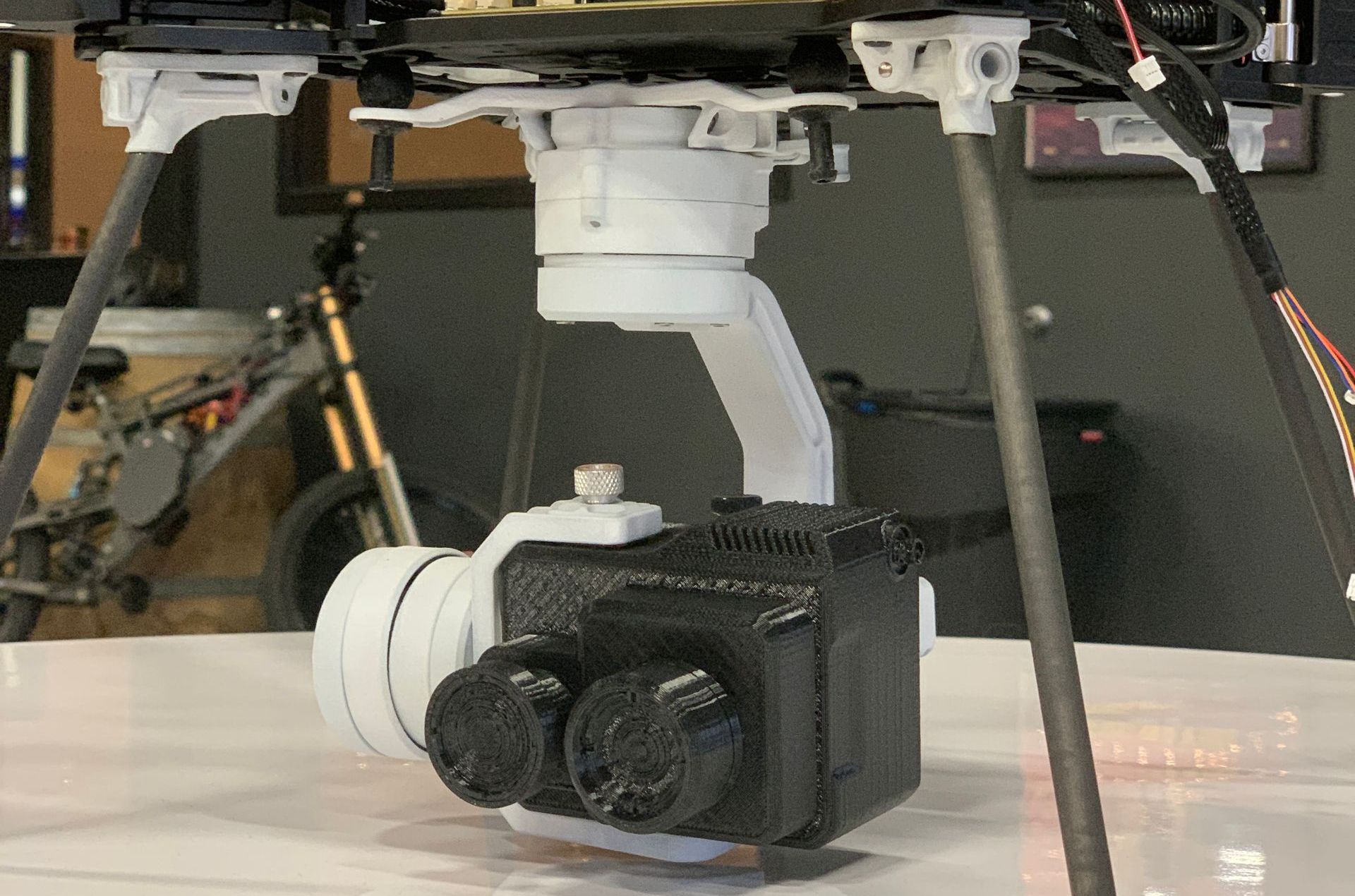
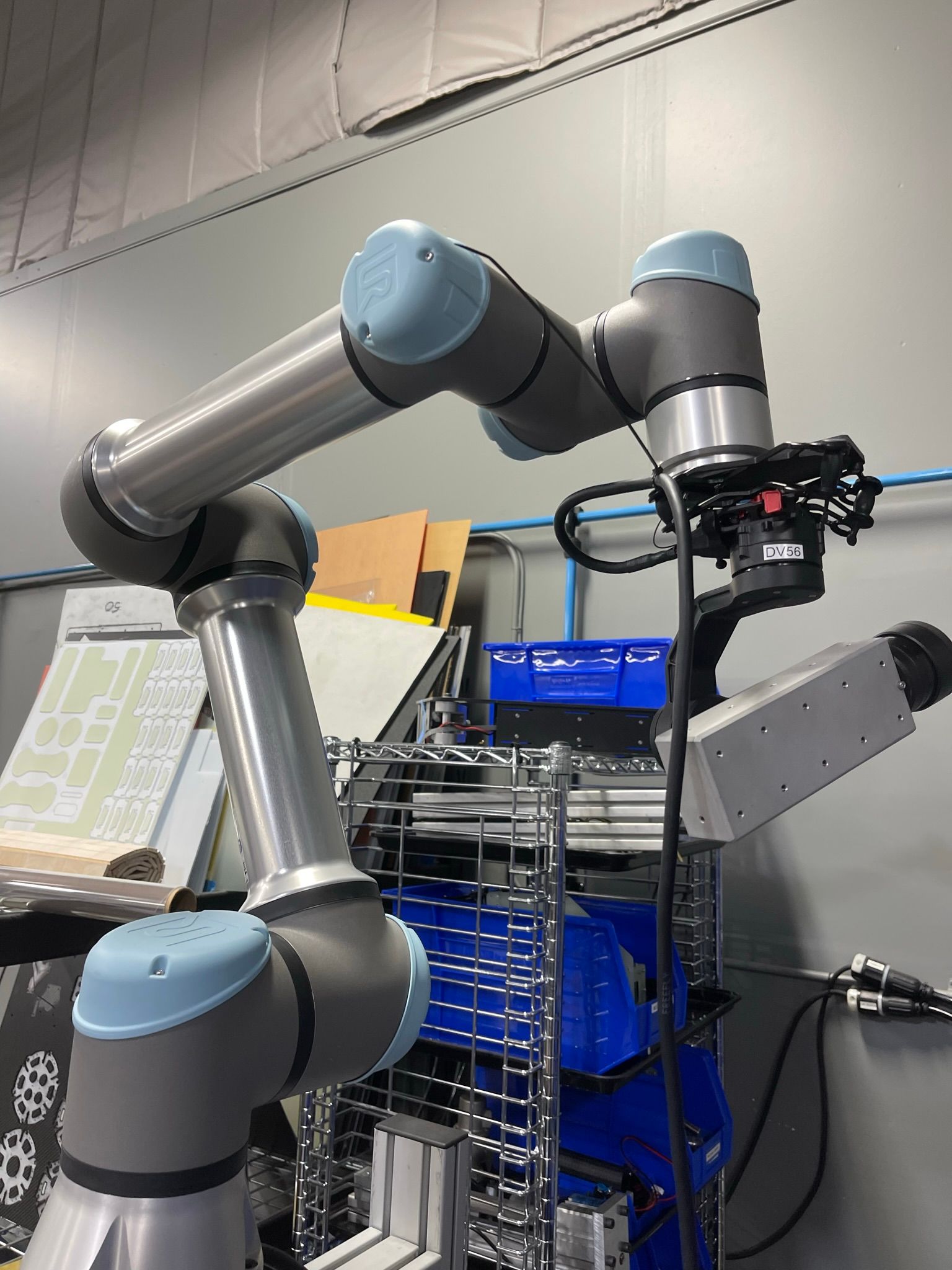
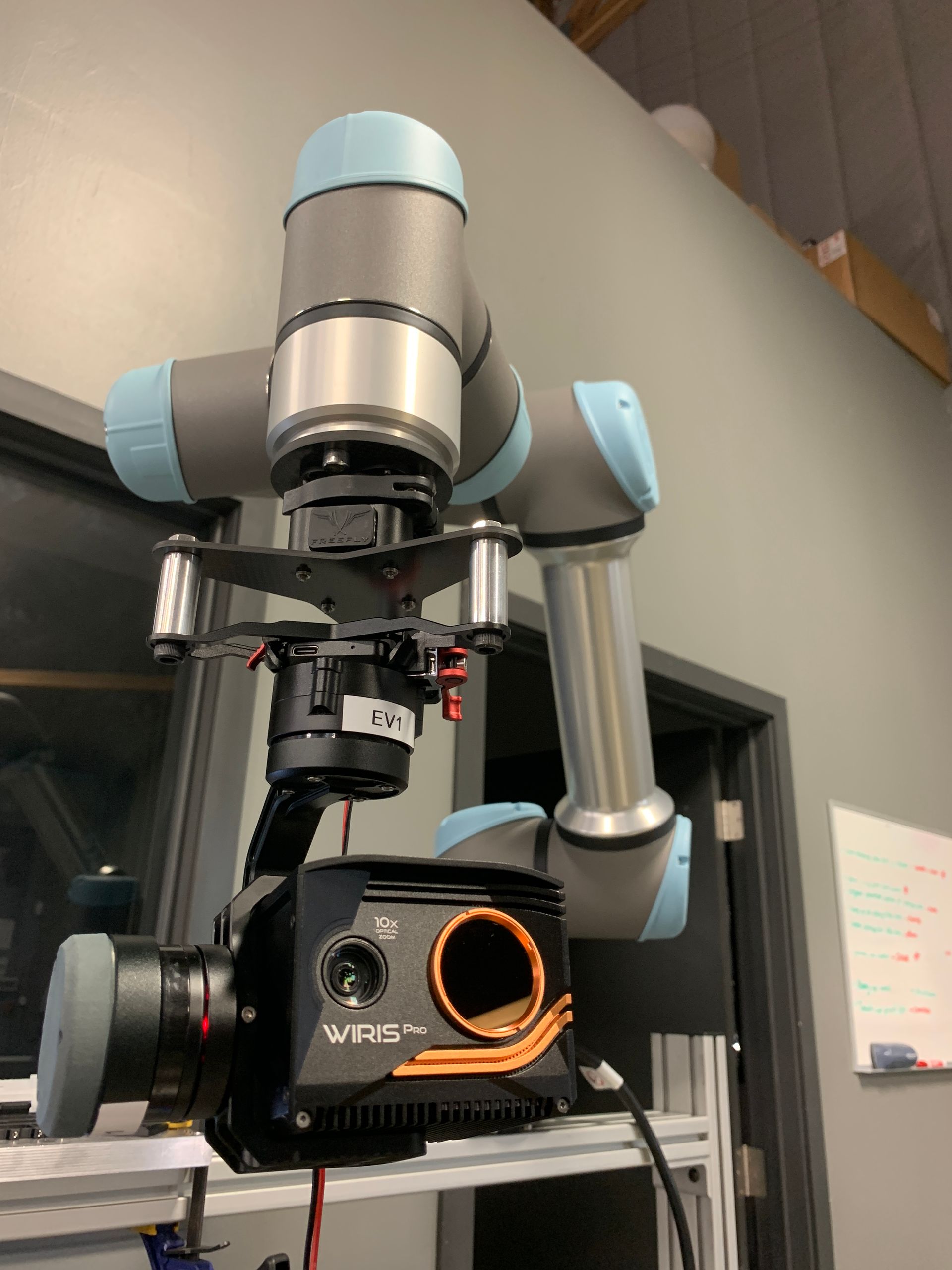
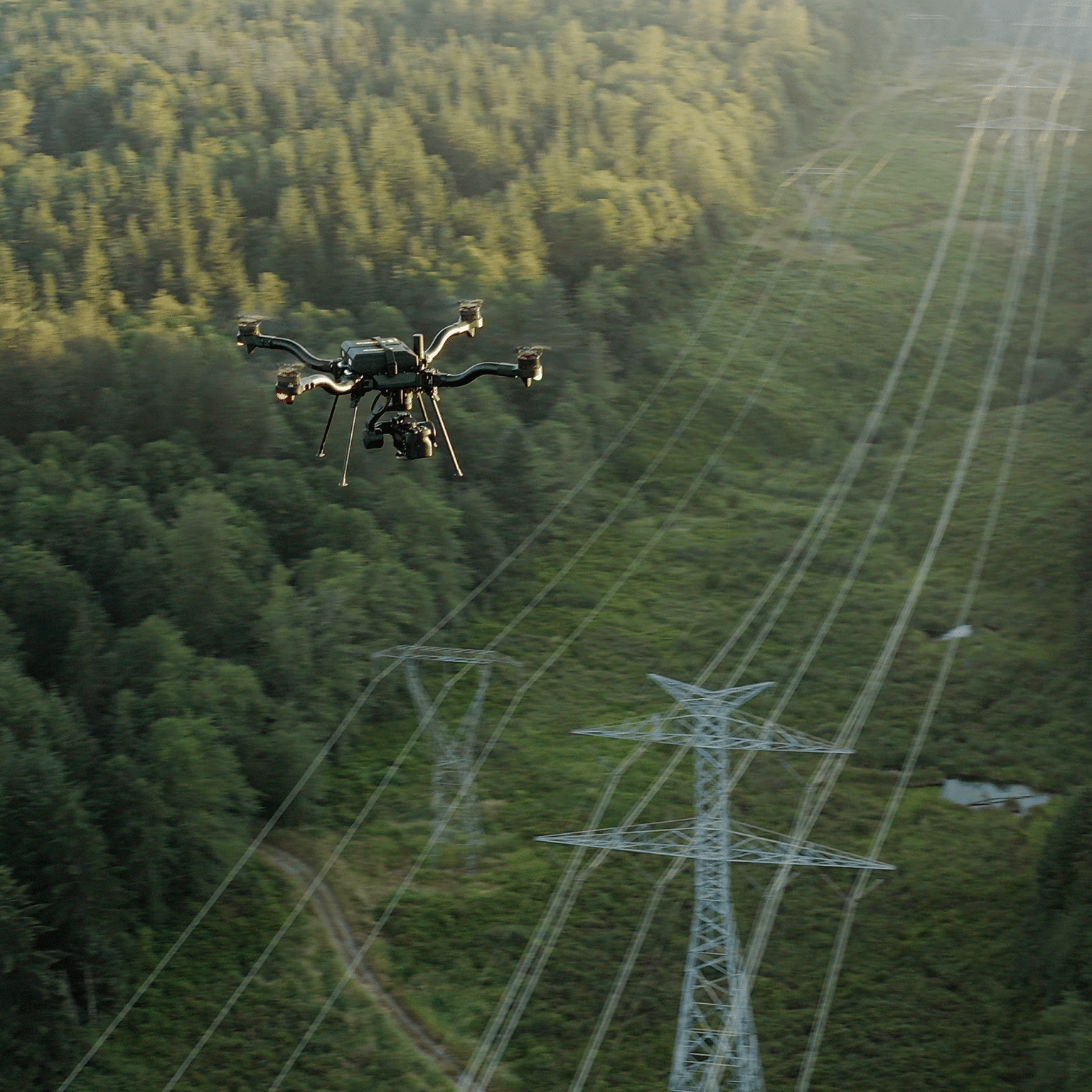
Following Astro's successful launch to production, I turned my attention to the Mini Gimbal project. The creation of a Mini Gimbal would enable Astro to be a fully integrated UAS solution. Historically customers would have to piecemeal their solutions together from multiple vendors, sometimes even modifying the parts in order to get the integration to fully function. By including an integrated gimbal into Astro, along with a bespoke smart battery, and swappable gimbal payloads, we were able to fill a need from customers across industries and verticals. Ultimately the strategic decision to design the gimbal in-house ensured complete control over the product's design, interface, user experience, and weight optimization.
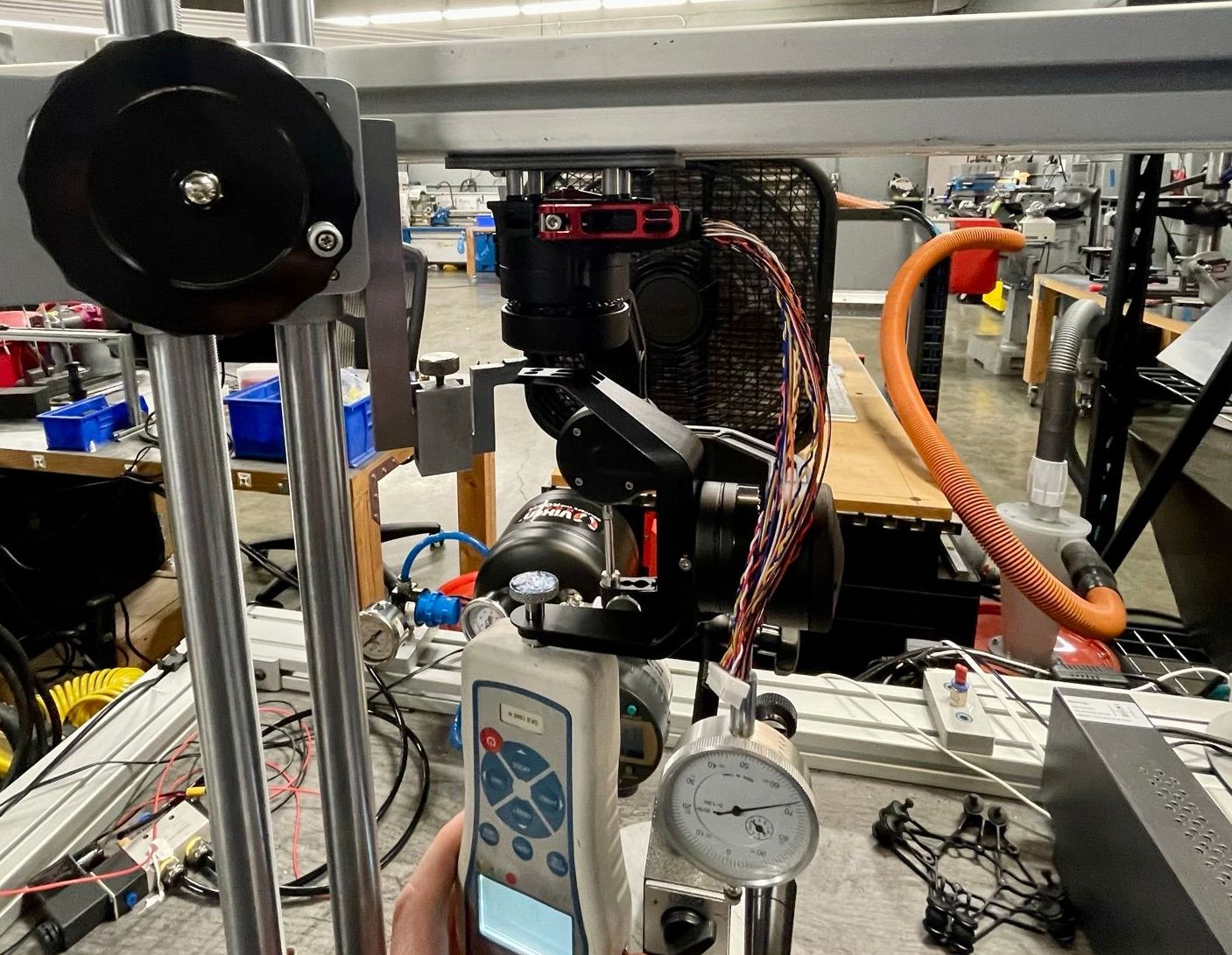
Leveraging the engineering team’s experience from previous gimbal projects like Carbon, XL, Pro, and Cinema Robot, the Mini Gimbal's design was completed during a two-week break in Astro's schedule. My responsibilities included designing the Astro to gimbal electromechanical interface, vibration isolation, packaging, and the pan motor assembly. During the break in Astro’s schedule, engineering validation was conducted on the gimbal, while leading effort organizationally I also conducted the gimbal stiffness, lifecycle, and interface testing. Once testing on the gimbal came to a close, the engineering team split to work simultaneously on the gimbal, battery, and Astro. I returned to Astro and lead its efforts over the final months before completion.
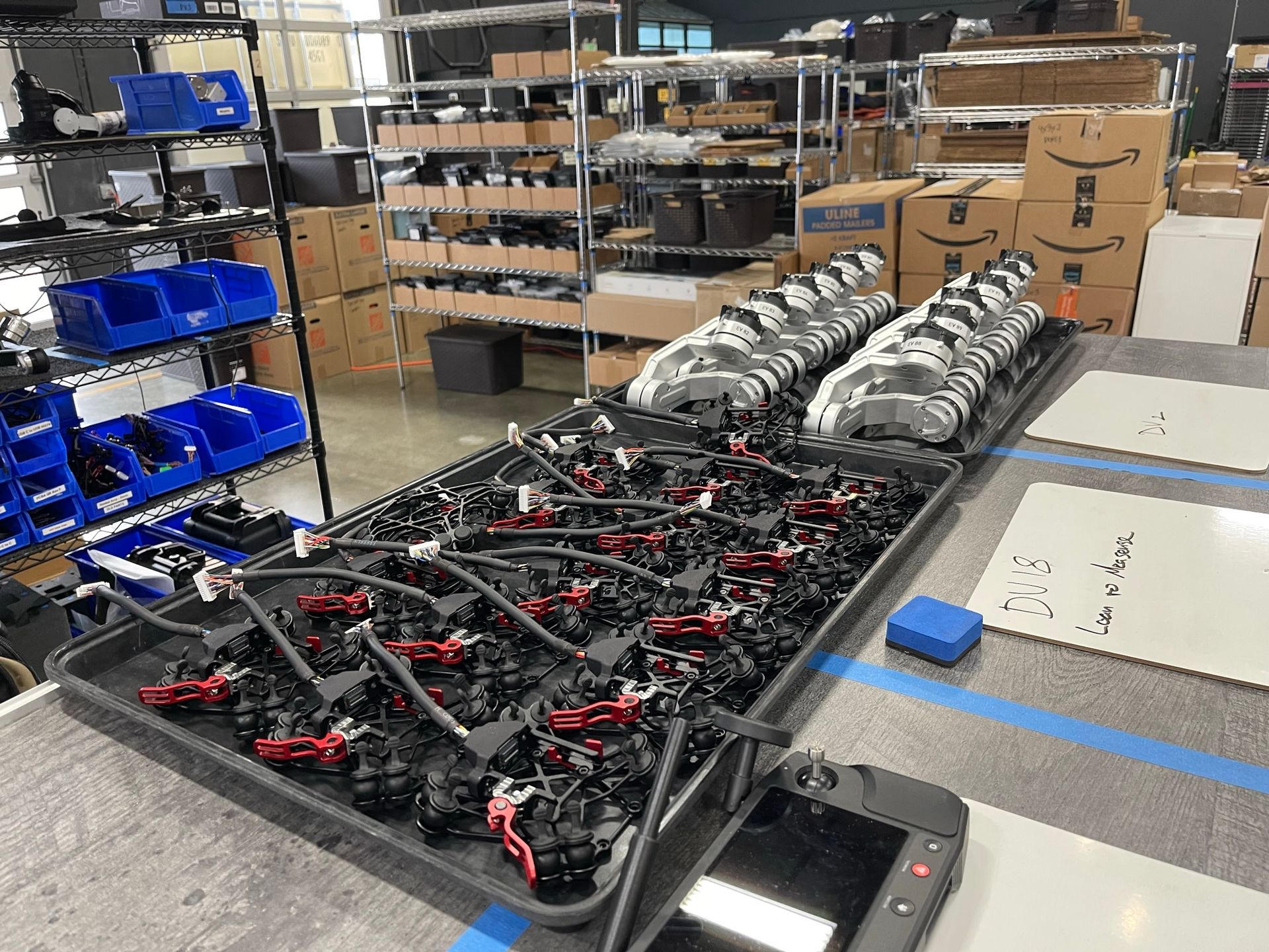
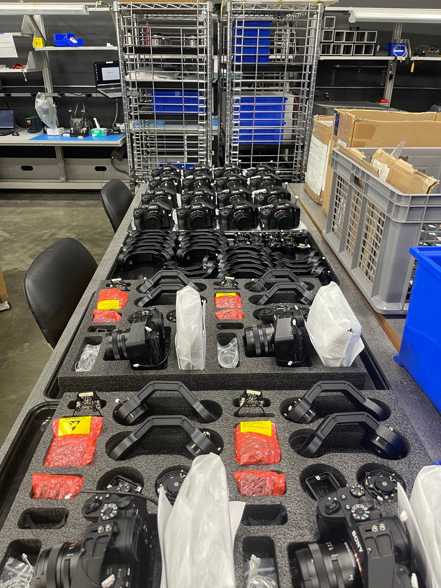
Following Astro's successful progression to the mass production stage, I turned my attention back to the Mini Gimbal project. This involved solving lingering issues including, deteriorating motor stiffness, resonance interactions between the aircraft and gimbal, and payload misalignment. At this point Astro and its smart battery were both waiting on the completion of the Mini Gimbal, requiring me to balance the gimbal’s transition to manufacturing with solving issues in the design. Fortunately I was able to strategically move ahead with key parts of the manufacturing preparation work while overcoming the design issues so no manufacturing work needed to be redone and the schedule was not extended by the lack of closure in engineering. My manufacturing ownership extended to creating a new manufacturing workflow, fixture design, and the establishment of a new production line workcell. To ensure success of this new line concept and process workflows, I stayed behind to oversee the assembly of the first 100 units. This allowed quick resolution of issues when they arose on the production line, including problems with IMU temperature calibration, programming glitches, and fixture modifications to ensure efficiency. While the Mini Gimbal was one of the smaller projects in terms of BOM size, complexity, and physical size, the repeated project handoffs, level of integration with Astro, and novelty of the production process made for a challenging project.
Team Size
6
Launch Date
5.19.22
Acres per Flight
220
Max Resolution
5mm
Key Challenges
Keep it Smooth and Stable (KISS: Erik’s Version)
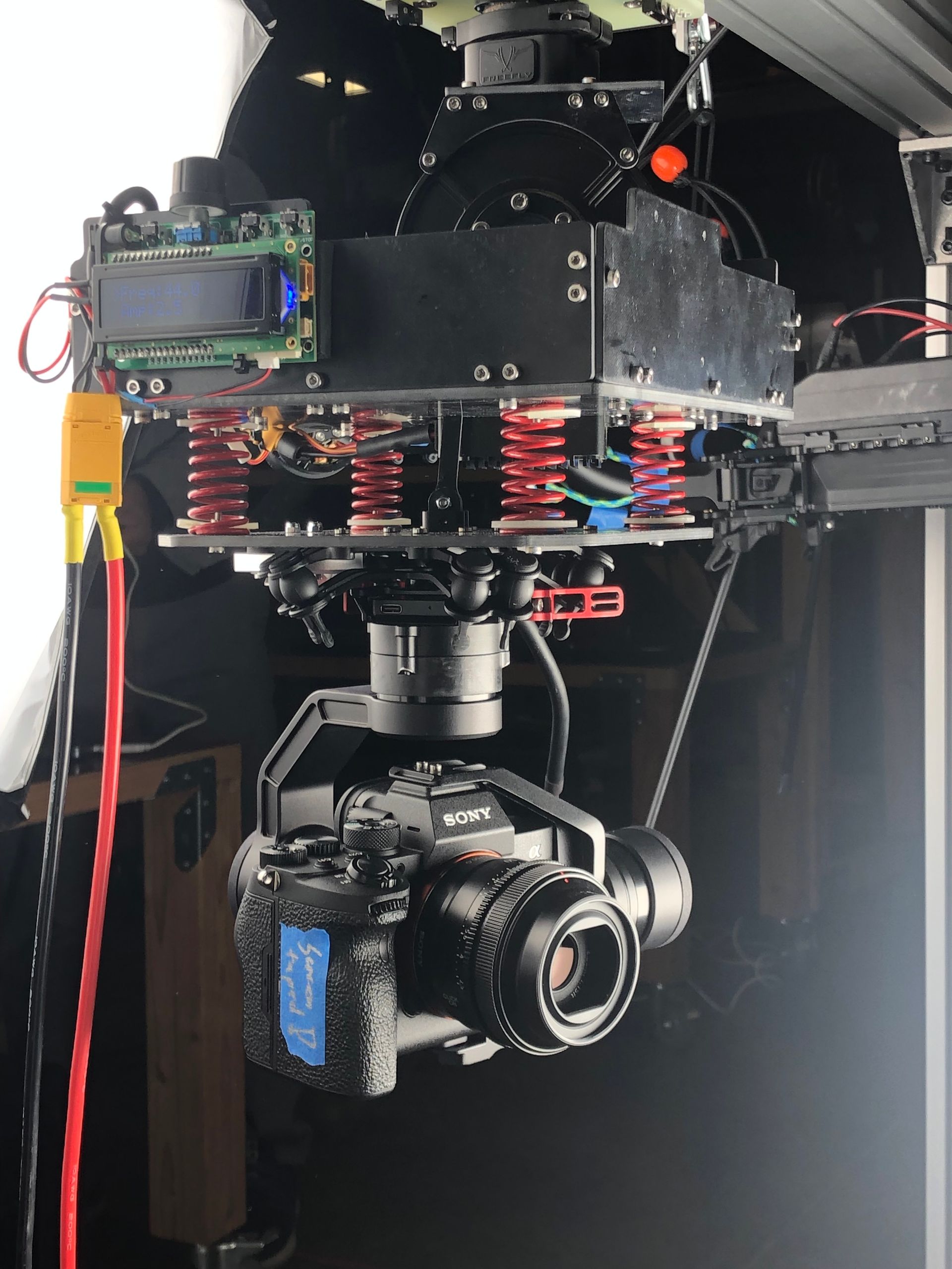
Designing the vibration isolation system is one of the hardest challenges for gimbals, and there is a whole industry which has evolved around this challenge. The process starts with an analysis of the vibrations being input on the system and assessing the limit of the gimbal's stabilization performance. In most cases the gimbal performance cannot keep up with the disturbances being imparted on it, thus you progress to the next step of the investigation where levers are pulled to ensure the gimbal performance can stay ahead of the disturbances.
There are many ways to arrive to such a system, and here are some of the ones I tested out for the Mini Gimbal:
- Reduce the amplitude of or shift the vibration spectrum coming into the system from the aircraft.
- Increase gimbal stiffness to improve performance of the gimbal control loop.
- Tune the isolator to remove the inciting frequencies and reduce energy in the vibration profile.
- Increase the speed of the control loop.
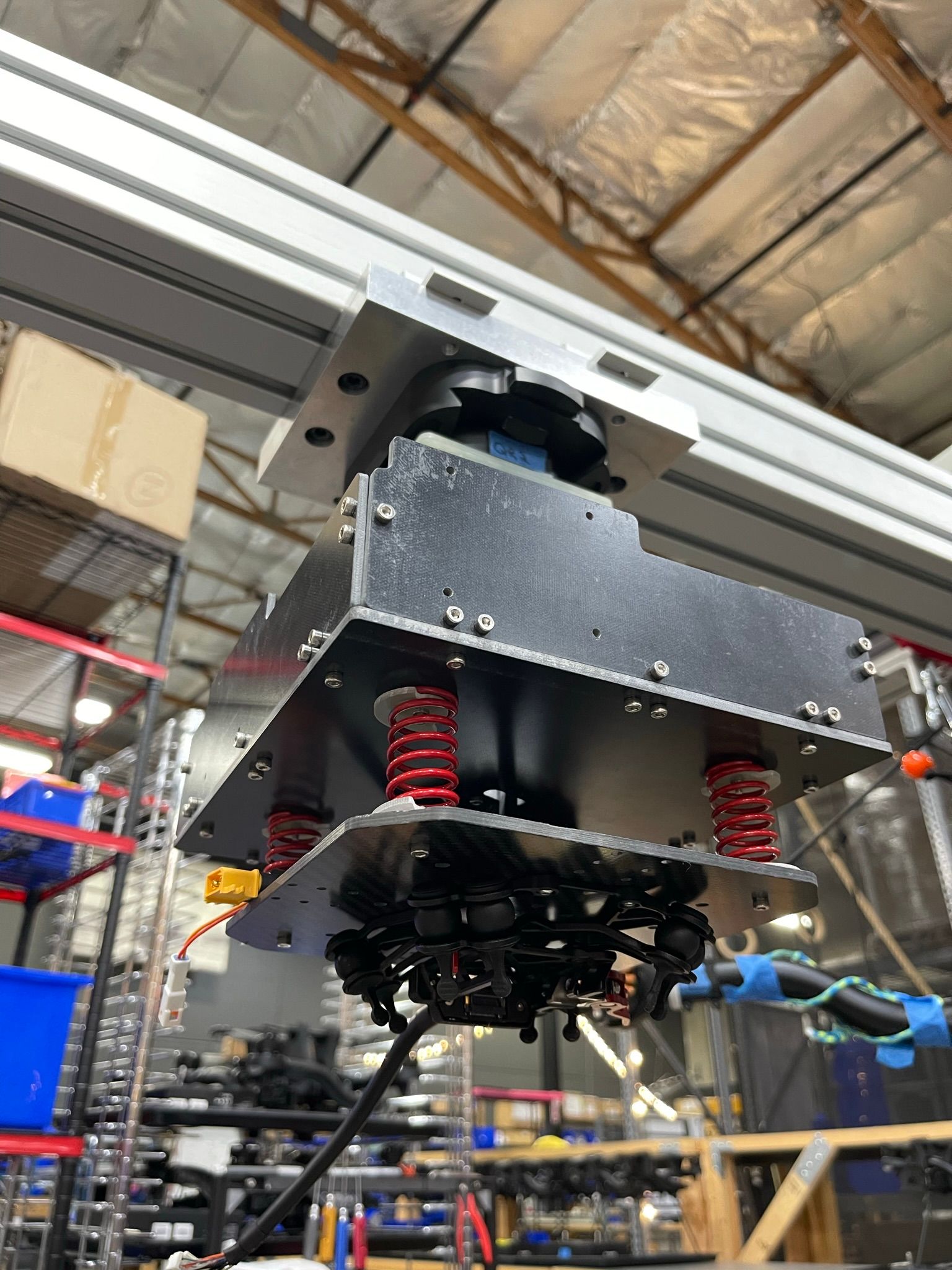
This specific instance of the problem had an additional challenge where the system vibrations could also not upset the in-body image stabilization of the Sony A7R4. I used an iterative process to find a solution, building a hanging vibration table to input specific vibration spectrums into the prototype isolators that could resemble the vibrations coming from an Astro. Then validating the designs with hours of flight testing to confirm the results from the vibration table.
The vibration isolation solution for Mini Gimbal consisted of two parts:
- Custom gel-filled dampers filled with a substance that plays nice with silicone, is non curing, and has damping characteristics specific to this application.
- The ability to fine tune the isolator to a payload by varying the quantity of dampers as well as their durometer.
Designing for the Future
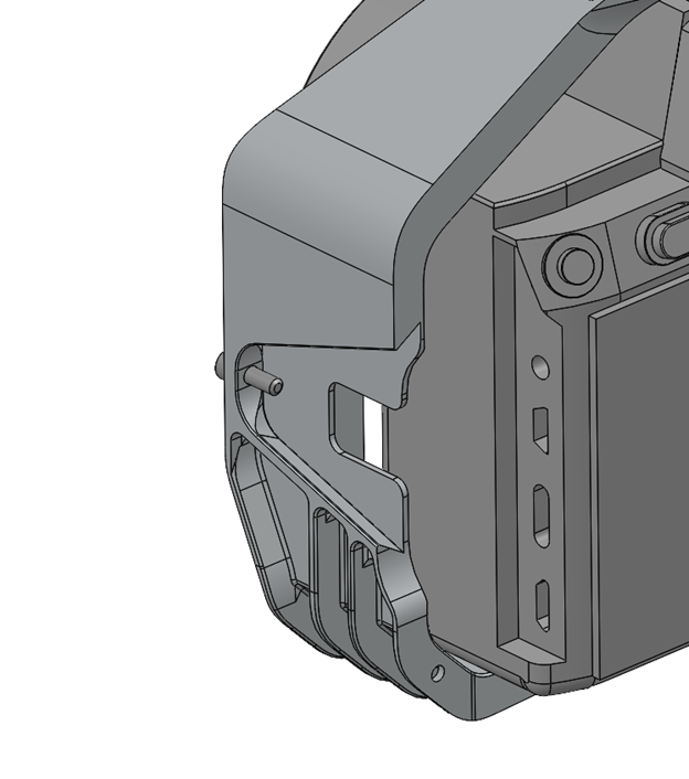
One of the primary motivations for developing the Mini Gimbal in-house was to allow users to swiftly interchange various payloads. Not only would this benefit customers, it would also help keep the manufacturing workflow streamlined, reduce the amount of different parts stocked in inventory, and allow us to lower the cost of the gimbal using manufacturing techniques better suited to higher volumes.
There would be a few challenges to overcome in this endeavor, the easiest being designing the mechanical mechanism itself. Before starting any design work I analyzed the scoped payloads for size, mass, and center of gravity; this in addition to constraints set by Astro allowed me to come up with the bounding parameters for payloads that we could integrate.
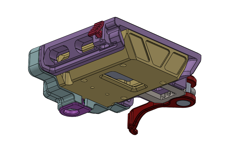
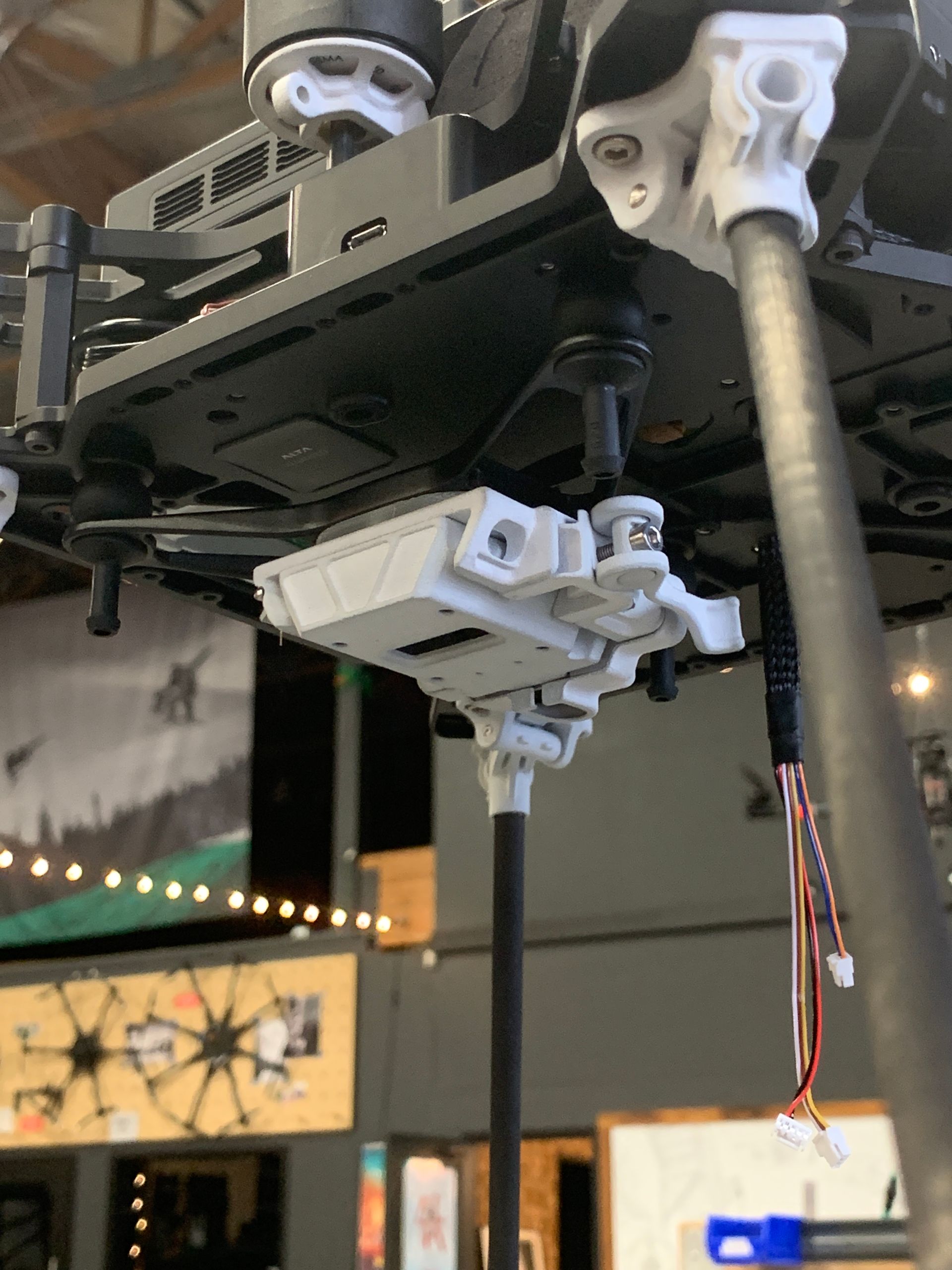
Once those parameters were in place the mechanism design could commence. The concept was a tapered dovetail on the gimbal and corresponding socket on the payload mount; this mount provided a self-locating joint which could be consistently repeated for many cycles.
Finally, in order to ensure the gimbal and payload would be well balanced (crucial in gimbal design as any imbalance will cause unnecessary motor loading), the center of gravity (C.G.) of both the gimbal and payload needed to be known. To accurately determine the C.G. for each payload, I employed a method involving suspending the payload with a thin fishing line from multiple points, capturing photos of its equilibrium position, and overlaying these images to identify the intersection point of the lines. While the payloads' C.G. values were obtained experimentally, the gimbal's C.G. was calculated using precise weight and material specifications for each component in the CAD model, including screws, cables, PCBAs, and other manufactured parts. Leveraging this C.G. data, I was able to design payload mounts that align the payload's C.G. within 0.2mm of the gimbal's C.G., ensuring optimal balance.
A Fine Balance Between Weight and Rigidity
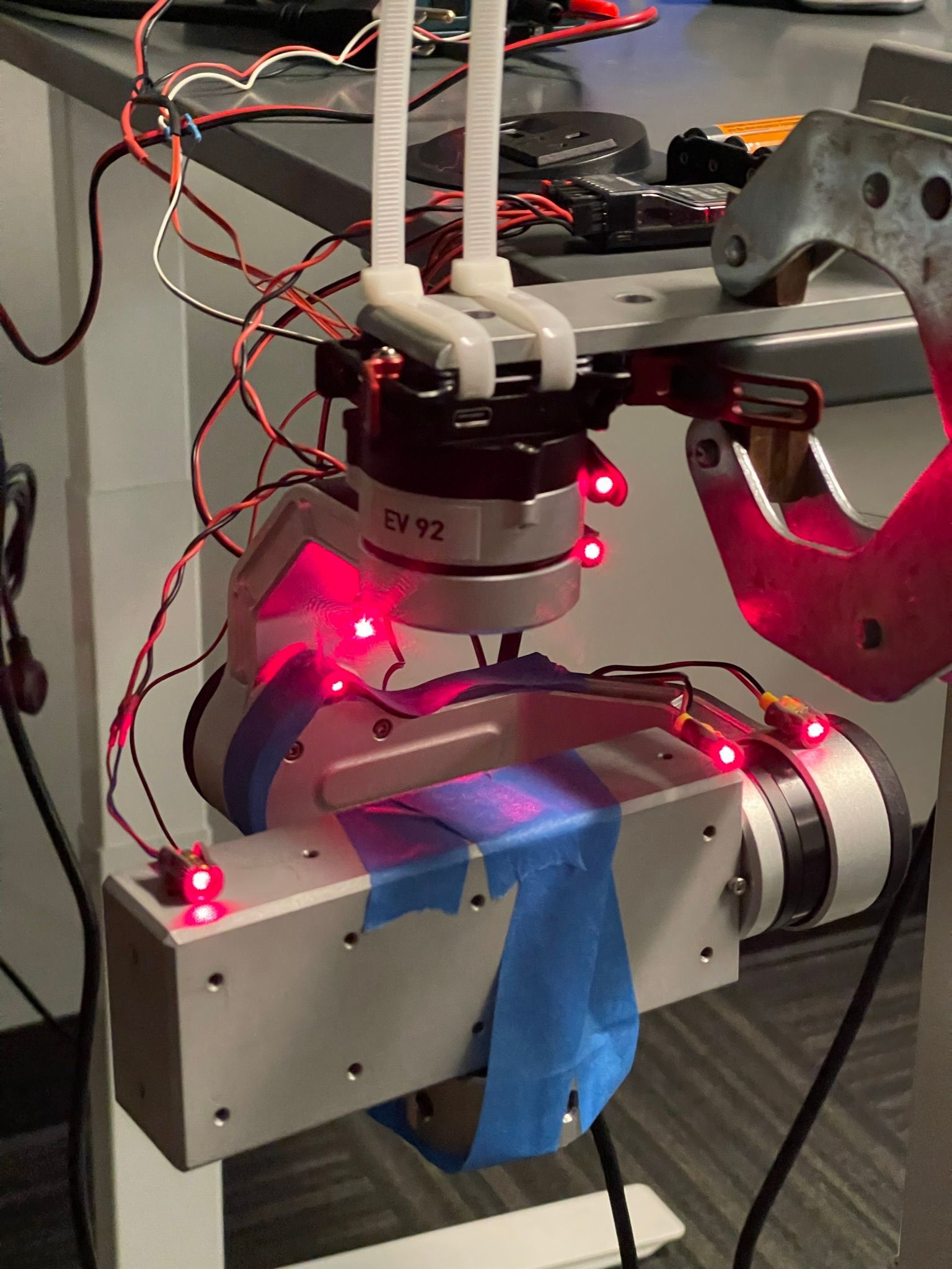
You can picture a gimbal as a system made up of several springs in a series. This system’s objective is to detect a disturbance input at one end of the spring system as quickly as possible from the other end. The ideal scenario is that the entire gimbal is infinitely stiff so disturbances are instantly detected, allowing the control loop to respond to the disturbance knowing the exact state of the entire system. However, gimbals which are flown need to be light; every superfluous gram adds up and a penalty is paid in flight time. This trade off between stiffness and weight is a key challenge when designing gimbals, especially ones which are airborne.
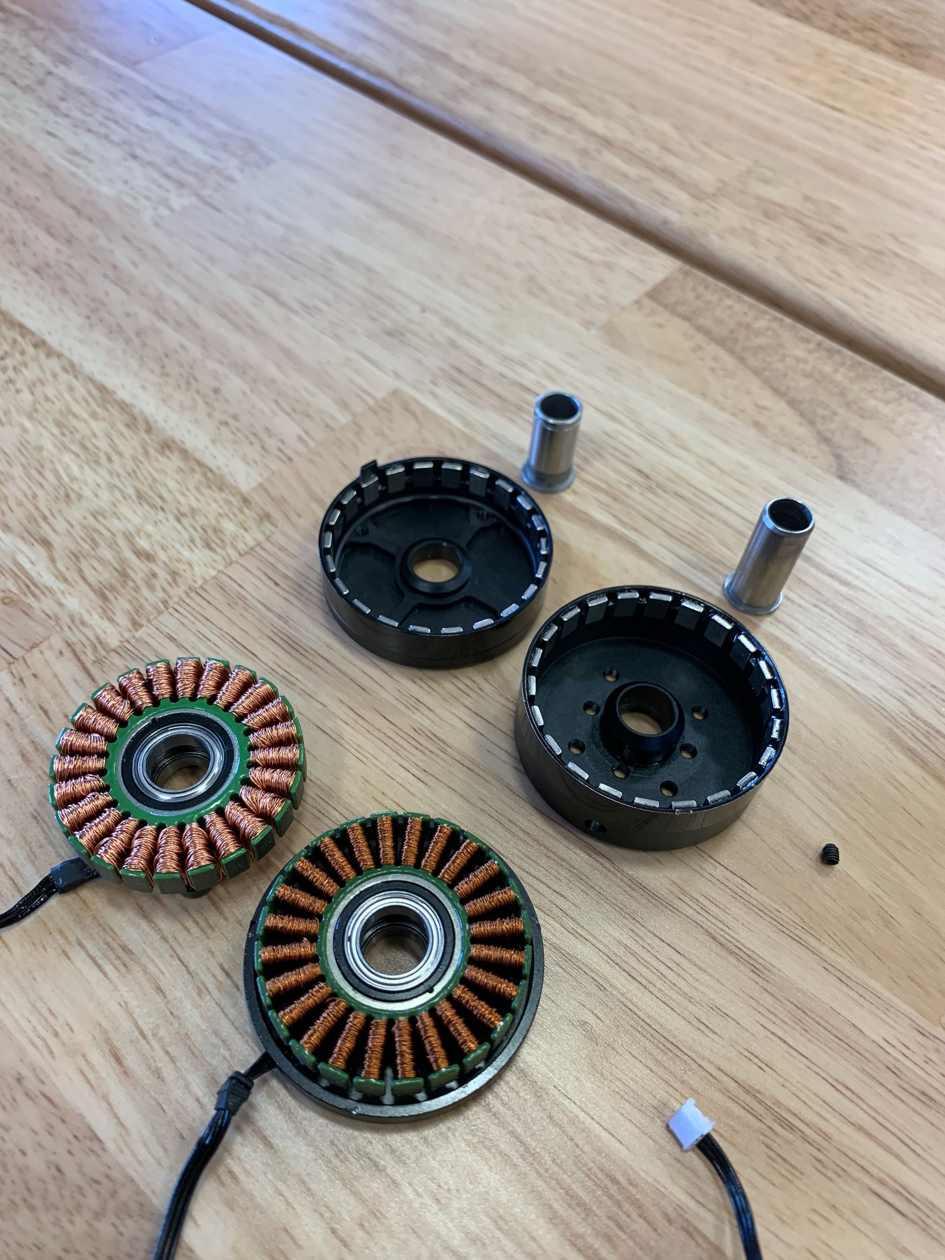
After receiving and testing the first prototype of Mini Gimbal, the motor, arms, and payload dovetail design were highlighted as areas that did not meet the minimum resonant frequency target (stiffness metric). Motors are often one of the more flexible parts of a design since they need to be dynamic.
However, through an investigation to find the root cause of the lack of stiffness I found some key design issues that needed to be changed in order for the motors to meet the stiffness requirements:
- The springs preloading the motor stack were being compressed and plastically deformed resulting in less preload force than intended. The solution was to source a better spring and test them for adequate preloading and the ability to compress to nearly flat state without plastically deforming.
- The bearing spacing on the stator's shaft was undersized resulting in a poor ability to react to bending forces on the motor bell. Solving this issue required a substantial design change to the stator mount; the max bearing spacing was also limited by other constraints in the gimbal and motor.
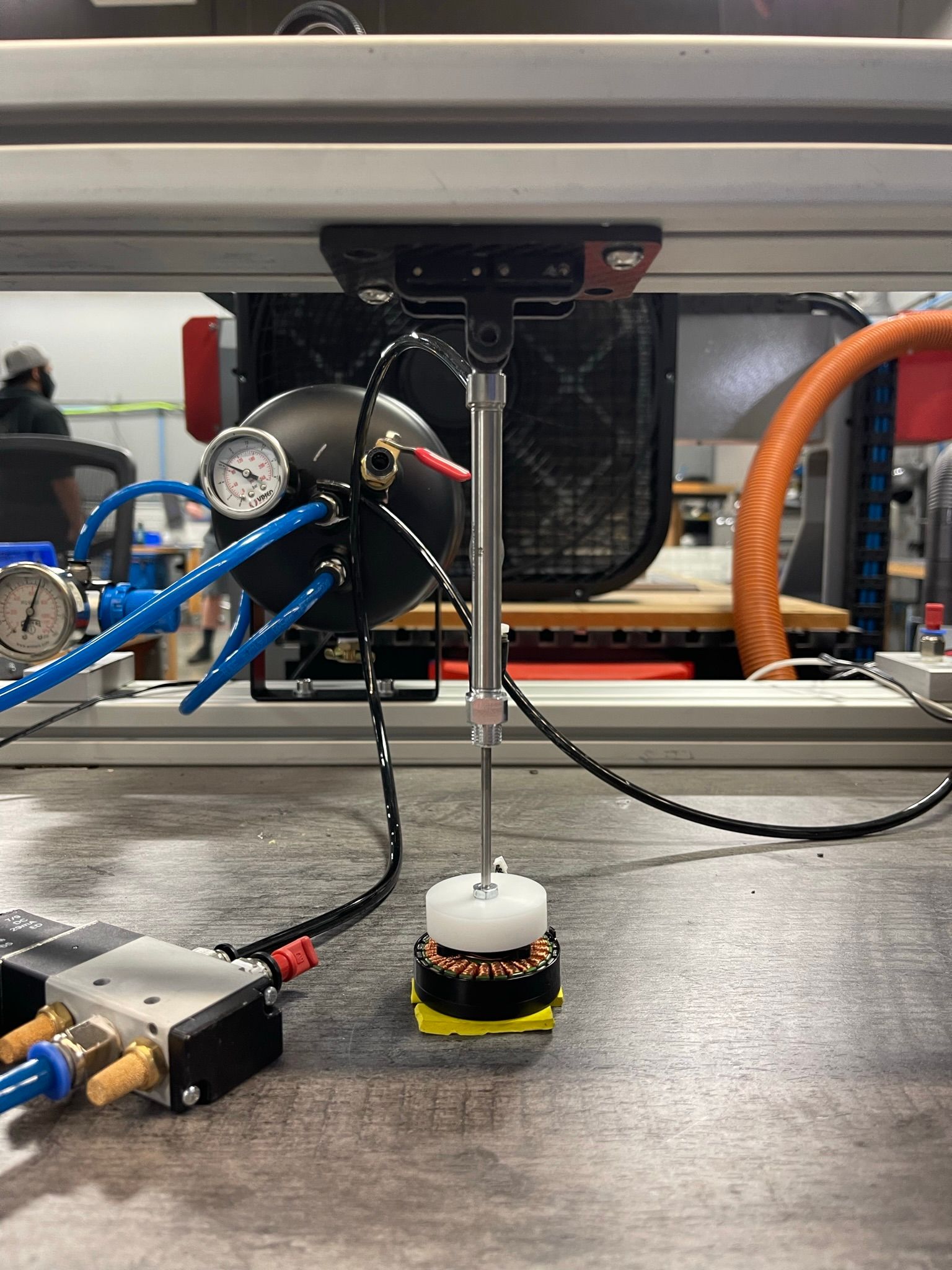
- The shaft's press fit into the motor bell was incorrectly sized causing it to break free after extended periods of use. This coupled with the deformed preload spring resulted in a motor that had more than 1mm of axial play once the shaft came free. I solved this by adjusting the fit between the shaft and bell as well as adding bearing loctite to the joint.
The issues with the gimbal arms and dovetail required more cross section to withstand the bending caused by the weight of the payload. After implementing these modifications and testing the second gimbal iteration, I confirmed the revised design met the expected performance standards and achieved the target gimbal stiffness.
